
Movable sealing position compensation device

A compensation device, dynamic sealing technology, applied in the direction of engine sealing, fluid pressure actuating device, engine components, etc., can solve the problems of leakage, compensation discount, increase cost, etc.

Pending Publication Date: 2019-05-10
LANZHOU UNIVERSITY OF TECHNOLOGY +1
View PDF0 Cites 2 Cited by
  • Summary
  • Abstract
  • Description
  • Claims
  • Application Information

AI Technical Summary

Problems solved by technology

On the dynamic seal of some structures, springs or O-rings are installed on the outer side of the sealing ring as position compensation, but both the springs and O-rings will be deformed to fatigue under long-term compression, which greatly reduces the compensation effect, resulting in leakage and isolation. Short-term replacement increases the cost, which is not conducive to long-term development

Method used


Image

  • Movable sealing position compensation device
  • Movable sealing position compensation device

Examples


Embodiment Construction

[0010] The present invention will be described in detail below in combination with specific embodiments.

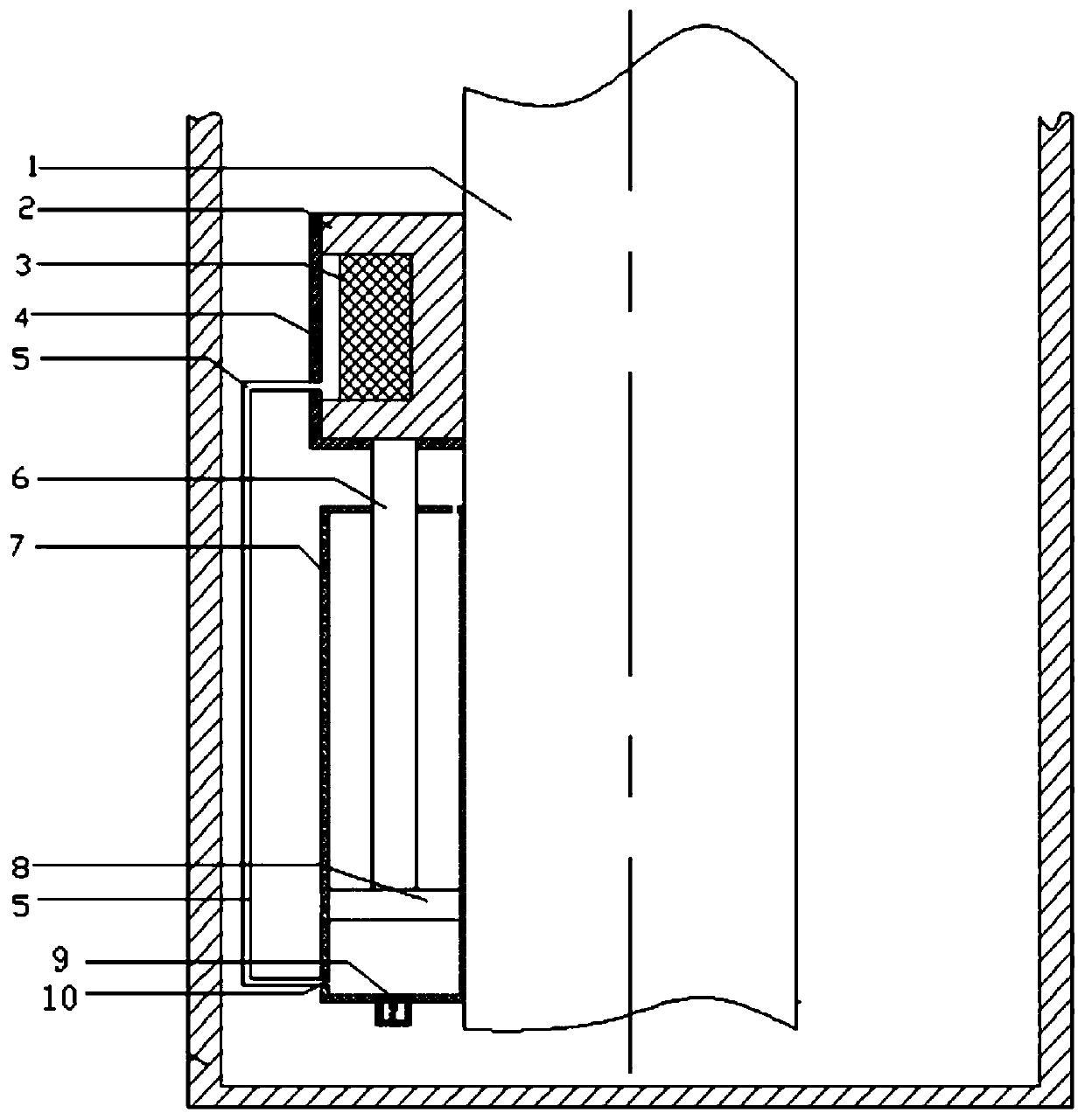
[0011] The present invention as figure 1 and figure 2 As shown, the piston rod 1 and the piston rod 1 are connected to the cylinder 7. The cylinder 7 is provided with a long rod 6 and a piston 8. There is a small hole above the cylinder 7. One end of the long rod 6 is connected to the piston 8, and the other end is connected through the small hole. sealing ring 2,

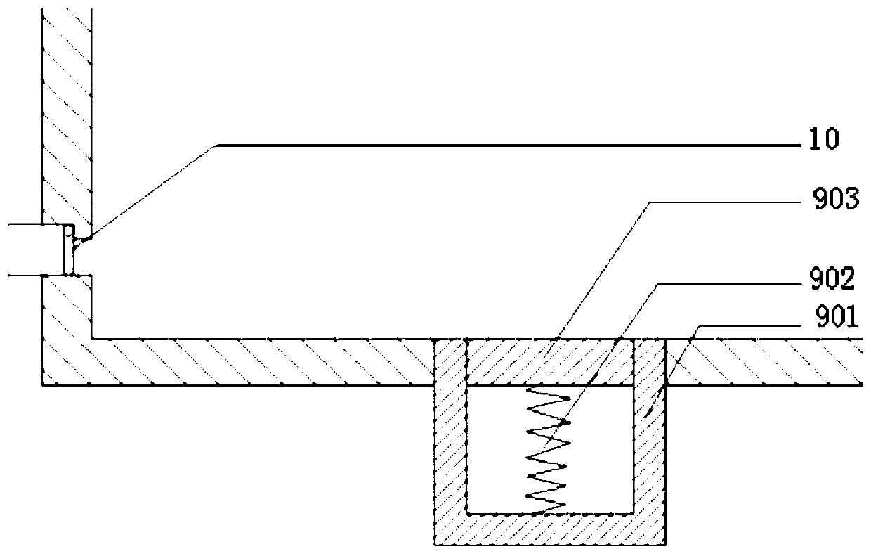
[0012] The sealing ring 2 is connected with the rubber ring 3, the sealing ring 2 is placed in the gland 4, there is a space between the rubber ring 3 and the gland 4, and the hollow tube 5 communicates this space with the space below the piston 8 in the cylinder 7. Excessive for preventing cylinder 7 air pressures, simple and easy safety valve 9 is housed at cylinder 7 bottom openings, guarantees that air pressure can not be excessive. An air core 10 is provided at the joint between the hollow tube 5 and ...


PUM


Abstract

The invention discloses a movable sealing position compensation device. A piston rod is connected with an air cylinder, a long rod and a piston are arranged in the air cylinder, the upper portion of the air cylinder is provided with a small hole, one end of the long rod is connected with the piston, and the other end of the long rod penetrates through the small hole and is connected with a sealingring; the sealing ring is connected with a rubber ring and arranged in a gland, a space is reserved between the rubber ring and the gland, it is guaranteed that the sealing ring has the enough air pressure to maintain the sealing state when the piston moves, and the space communicates with a space under the piston in the air cylinder through a hollow pipe; a simple safety valve is installed at anopening of the bottom of the air cylinder, and it is guaranteed that the air pressure can not be too large; and an air core is arranged at the joint of the hollow pipe and the lower portion of the piston of the air cylinder. The movable sealing position compensation device has the beneficial effects that the leakage problem caused by wear generated when the sealing ring does movable sealing reciprocating motion can be effectively solved, then the purpose of protecting the sealing ring is achieved, production losses are avoided, smooth conduction of whole production is facilitated, the structure is relatively simple, and the good practicability is achieved.

Description

technical field [0001] The invention belongs to the technical field of mechanical equipment and relates to a device for moving a large piston rod at a medium and low speed. Background technique [0002] With the development of science and technology, domestic and foreign attach great importance to the development of sealing technology, and have achieved results, such as the "sock seal" device of Philips in the Netherlands and the new sliding sealing device of Sweden's United Stirling Engine Company. The latter has low cost and long life. On the dynamic seal of some structures, springs or O-rings are installed on the outer side of the sealing ring as position compensation, but both the springs and O-rings will be deformed to fatigue under long-term compression, which greatly reduces the compensation effect, resulting in leakage. Short-term replacement increases the cost, which is not conducive to long-term development. Contents of the invention [0003] The purpose of the...

Claims


Application Information

Patent Timeline
IPC IPC(8): F16J15/24F15B15/20
Inventor 杨东亚田松李伟涛熊新稳李瑞红
Owner LANZHOU UNIVERSITY OF TECHNOLOGY
Learn More