Induction cooker testing facility

A technology for testing equipment and induction cookers, applied in lighting and heating equipment, household stoves/stoves, electric heating fuels, etc., can solve the problems of large test errors, large manual influences, large time errors, etc., to improve accuracy and avoid manual labor. wasteful effect

Inactive Publication Date: 2019-05-10
GUANGZHOU SANTUO IDENTIFICATION TECH CO LTD
View PDF7 Cites 0 Cited by
  • Summary
  • Abstract
  • Description
  • Claims
  • Application Information

AI Technical Summary

Problems solved by technology

[0002] The existing test method is manual testing. By manually selecting and controlling the function status of the induction cooker, there will generally be a large time error. In the long-term life test of the induction cooker, the artificial influence is large, resulting in large test errors and single test data, which is difficult to obtain. The data involved in the test, such as water level, heating temperature, power, failure time, etc., bring difficulties to the data analysis of the induction cooker;

Method used


Image

  • Induction cooker testing facility
  • Induction cooker testing facility
  • Induction cooker testing facility

Examples


Embodiment 1

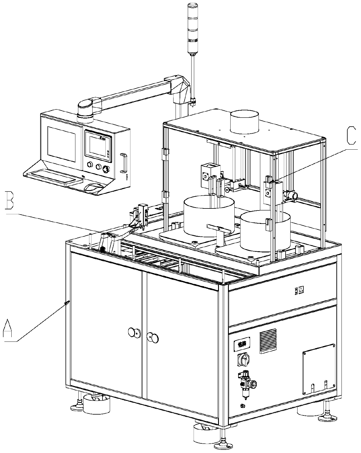
[0024] The electromagnetic oven test equipment used in the present invention includes: a frame A with functions of waterproofing, drainage, and steam drainage, a touch module B for controlling the induction oven, and a monitoring module C for monitoring the state of the induction oven.

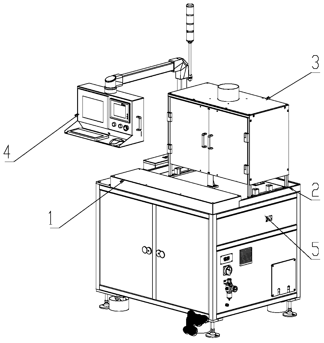
[0025] The frame A includes a waterproof casing 1, a drain tank 2, a water vapor shield 3, an operation panel 4, and a socket 5.

[0026] The touch module B includes a stylus 6 , an X movement axis 7 and a Y movement axis 8 . With programming function, test steps can be written.

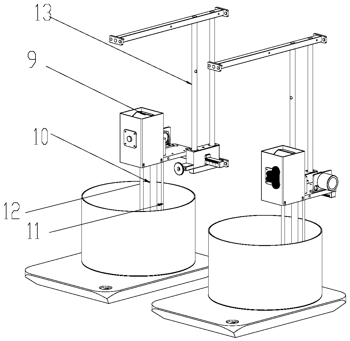
[0027] The monitoring module C includes a water level control component 9 , an automatic water injection component 10 , a temperature monitoring component 11 , a power monitoring component 12 , and a height adjustment component 13 . With real-time monitoring function, it can query the working status of the induction cooker in real time. Power monitoring assembly 12 is located within rack A. As shown in FIG. The he...

Embodiment 2

[0030] Such as Figure 1-4 The induction cooker test equipment shown includes a rack A, on which an induction cooker is placed, and a monitoring module C is covered outside the induction cooker, and a touch module B is arranged on the front side of the induction cooker. Equipped with a movable pot body.

[0031] The touch module B includes an external shell 1 , and the touch module B also includes a stylus 6 that can move along the X-axis and the Y-axis.

[0032] The touch module B includes an X moving shaft 7, and an X-axis slider driven by a driving device is arranged on the X moving shaft 7 .

[0033] A Y moving shaft 8 is installed on the X-axis slider, and the Y moving shaft 8 is provided with a Y-axis slider driven by a driving device to move along the Y-axis direction, and the stylus 6 is fixed on the Y-axis slider through a linkage mechanism. superior.

[0034] A socket 5 is provided on the side of the frame A, and the device also includes an operation panel 4 exten...


PUM


Abstract

The invention provides an induction cooker testing facility. The induction cooker testing facility comprises a machine frame. Induction cooker placement positions are arranged on the machine frame, monitoring modules cover the exteriors of the induction cooker placement positions, a touch control module is arranged at the front sides of the induction cooker placement positions, and movable pan bodies are arranged on induction cookers. The induction cooker testing facility has the functions of water resistance and drainage, water vapor emission, automatic water injection and the like, can achieve real-time monitoring of parameters such as the water level, the temperature, the power and the time, outputs testing data as required, effectively avoids the manpower waste caused in the manual testing process and the body injury of testing personnel, and supports the testing of double induction cookers and the programming of the testing procedures. By means of the induction cooker testing facility, multiple data can be acquired, and the accuracy of data analysis is effectively improved.

Description

technical field [0001] The invention relates to the field of monitoring equipment, in particular to an induction cooker testing equipment. Background technique [0002] The existing test method is manual testing. By manually selecting and controlling the function status of the induction cooker, there will generally be a large time error. In the long-term life test of the induction cooker, the artificial influence is large, resulting in large test errors and single test data, which is difficult to obtain. The data involved in the test, such as water level, heating temperature, power, failure time, etc., bring difficulties to the data analysis of the induction cooker; Contents of the invention [0003] The invention provides an electromagnetic oven testing device, which solves the problems in the prior art. [0004] Technical scheme of the present invention is realized like this: [0005] The induction cooker test equipment includes a frame, the rack is provided with an in...

Claims


Application Information

Patent Timeline
Patent Type & Authority Applications(China)
IPC IPC(8): F24C7/08
Inventor 顾华钟文勇兰力
Owner GUANGZHOU SANTUO IDENTIFICATION TECH CO LTD
Why Eureka
Try Eureka