Diagnosis system used for load circuit, and electric car

A load circuit and diagnostic system technology, applied in electrical testing/monitoring and other directions, can solve problems such as circuit board burnout, relay adhesion and false alarms, etc., to improve reliability and stability, and solve the effect of circuit board burnout

Active Publication Date: 2019-05-10
SVOLT ENERGY TECHNOLOGY CO LTD
View PDF9 Cites 4 Cited by
  • Summary
  • Abstract
  • Description
  • Claims
  • Application Information

AI Technical Summary

Problems solved by technology

[0006] In view of this, the present invention aims to propose a diagnostic system for load circuits and electric vehicles to solve the problem of relay adhesion false alarms in the process of high-voltage acquisition diagnosis by switching diff

Method used


Image

  • Diagnosis system used for load circuit, and electric car
  • Diagnosis system used for load circuit, and electric car
  • Diagnosis system used for load circuit, and electric car

Examples


Embodiment Construction

[0034] It should be noted that, in the case of no conflict, the embodiments and features in the embodiments of the present invention can be combined with each other.

[0035] At present, most electric vehicles use the first type of diagnostic circuit (reference ground is U01 or U02) to diagnose the electrical connection, and its structure and working principle will be introduced step by step below.

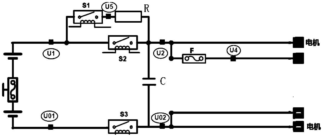
[0036] figure 1 It is a schematic diagram of the connection of a certain type of electric vehicle high-voltage electrical appliance in the prior art. In the figure, S1 is the pre-charging relay, S2 is the main positive relay, S3 is the main negative relay, R is the pre-charging resistor and F is the insurance. U01, U1, U02, U2, U4, and U5 are the high-voltage collection points respectively. The diagnosis principle is: the voltage of the battery pack can be obtained by collecting the voltage between U01 and U1; the state of the main and negative relays can be judged by collecting ...


PUM


Abstract

The invention relates to the field of control circuits, and discloses a diagnosis system used for a load circuit, and an electric car. The diagnosis system comprises a collection channel switching device and a controller, wherein the collection channel switching device comprises a switching module and a reference place switching module; the switching module is used for conducting or disconnectinga passage between a pressure-division circuit and a circuit where a sampling resistor is positioned; and the reference place switching module is used for switching the conducted passage to different reference places to conduct different collection channels. The controller is used for executing the following operations that: controlling a collection channel switching module to execute a switching operation; according to the voltage of sampling resistors on different sampling channels, determining voltage between different collection points and the corresponding reference place; comparing the determined voltage with the voltage of a battery pack; and according to a comparison result, determining the state of a corresponding relay or fuse. Therefore, different reference places are switched tosolve the problem of misinformation since relays are adhered in a high-voltage collection and diagnosis process through the switching of different reference places, and meanwhile, the problem that acircuit board is burnt out since a relay closing sequence is changed can be solved.

Description

technical field [0001] The invention relates to the field of control circuits, in particular to a diagnosis system for a load circuit and an electric vehicle. Background technique [0002] With the rapid development of the electric vehicle industry, the market has higher and higher requirements for the safety performance of electric vehicles. Whether it is a plug-in hybrid or a pure electric vehicle, the battery pack is its main source of power output. The voltage of the load circuit powered by the battery pack is generally relatively high, so the load circuit is usually called a high-voltage circuit. In addition, the battery pack is a relatively high-sealed environment. Therefore, in order to facilitate the vehicle operator to know whether the power output circuit of the battery pack is normal in real time, it is necessary to collect the voltage values ​​of each collection point from the high-voltage positive pole to the high-voltage negative pole circuit, each relay and i...

Claims


Application Information

Patent Timeline
IPC IPC(8): G05B23/02
Inventor 杨亚坤陈景涛王帅兵何强
Owner SVOLT ENERGY TECHNOLOGY CO LTD
Why Eureka
Try Eureka