Target polling position determination method and device

A technology for determining methods and targets, applied in two-dimensional position/channel control, etc., can solve problems such as low reliability, achieve the effect of improving safety and solving low reliability

Inactive Publication Date: 2019-05-10
STATE GRID BEIJING ELECTRIC POWER +2
View PDF14 Cites 7 Cited by
  • Summary
  • Abstract
  • Description
  • Claims
  • Application Information

AI Technical Summary

Problems solved by technology

[0004] Embodiments of the present invention provide a method and device for determining a target inspection location, so as t

Method used


Image

  • Target polling position determination method and device
  • Target polling position determination method and device
  • Target polling position determination method and device

Examples


Embodiment 1

[0027]According to an embodiment of the present invention, a method embodiment of a method for determining a target inspection position is provided. It should be noted that the steps shown in the flowcharts of the accompanying drawings can be implemented in a computer system such as a set of computer-executable instructions and, although a logical order is shown in the flowcharts, in some cases the steps shown or described may be performed in an order different from that shown or described herein.

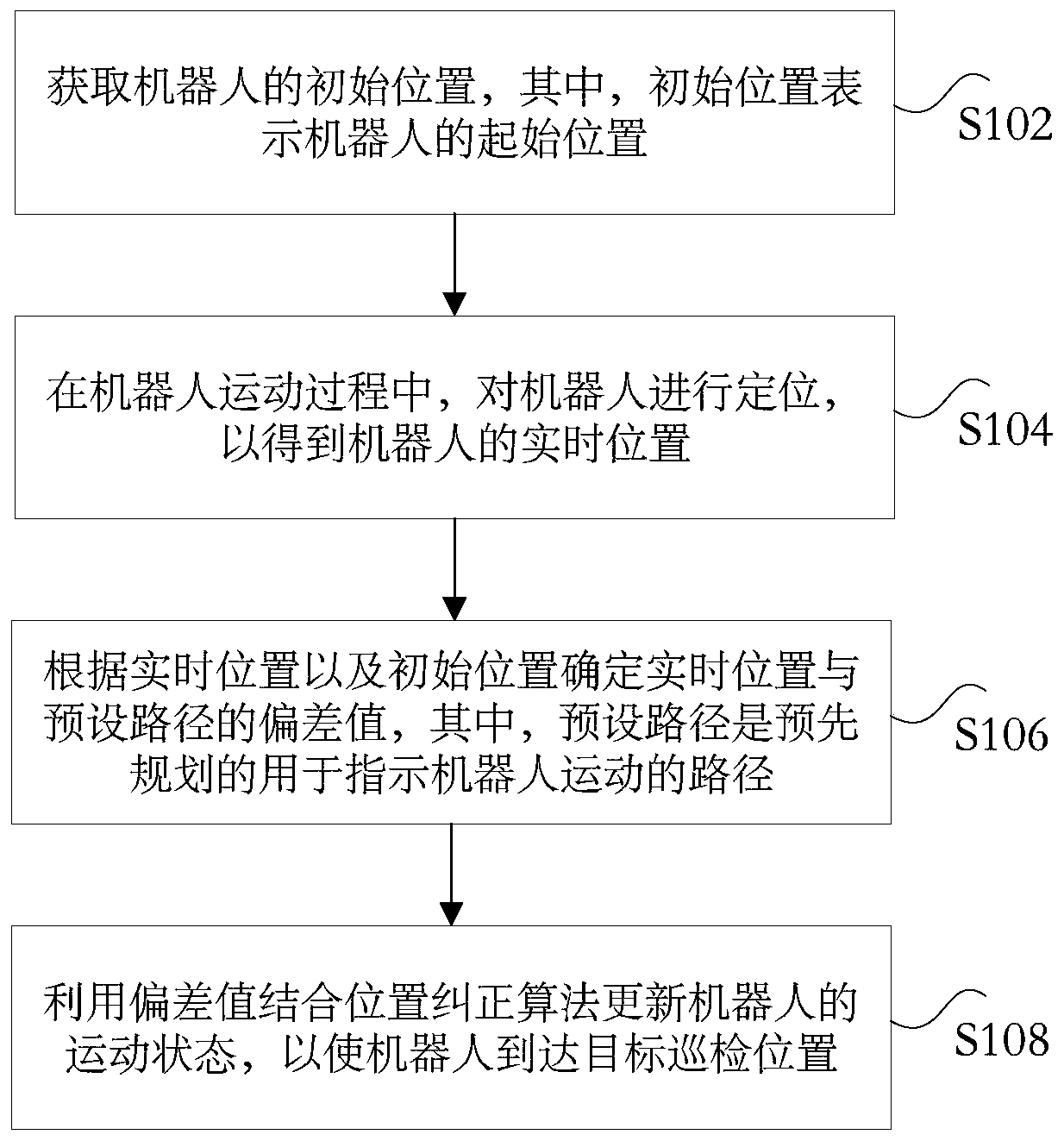
[0028] figure 1 is a flow chart of a method for determining a target inspection position according to an embodiment of the present invention, such as figure 1 As shown, the method for determining the target inspection position includes the following steps:

[0029] Step S102, acquiring an initial position of the robot, where the initial position represents the initial position of the robot.

[0030] In step S102, the positioning module can be used to first locate the starting pos...

Embodiment 2

[0060] According to the embodiment of the present invention, a device for determining the target patrol position is also provided. It should be noted that the device for determining the target patrol position in the embodiment of the present invention can be used to implement the target patrol position provided in the embodiment of the present invention. method of determination. The device for determining the target inspection position provided by the embodiment of the present invention is introduced below.

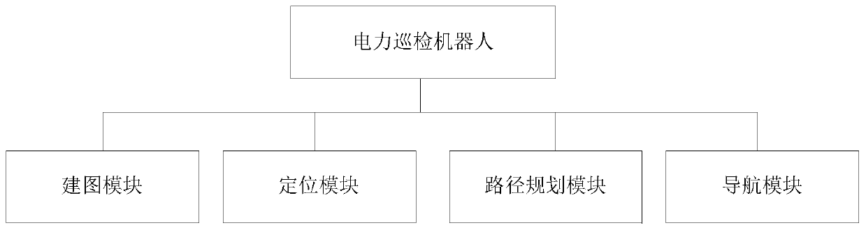
[0061] Figure 5 is a schematic diagram of a device for determining a target inspection position according to an embodiment of the present invention, such as Figure 5 As shown, the device for determining the target inspection position includes: an acquisition unit 51 , a positioning unit 53 , a first determination unit 55 and an update unit 57 . The device for determining the target inspection position will be described in detail below.

[0062] The obtaining unit 51 is...


PUM


Abstract

The invention discloses a target polling position determination method and device. The method comprises the steps of: obtaining an initial position of a robot, wherein the initial position expresses astarting position of the robot; positioning the robot in the motion process of the robot so as to obtain a real-time position of the robot; determining a deviation value between the real-time position and a preset path according to the real-time position and the initial position, wherein the preset path is a pre-planned path for indicating the motion of the robot; and updating the motion state ofthe robot by utilizing the deviation value and a position correction algorithm so as to ensure that the robot reaches a target polling position. According to the method and device, the technical problem that the manner of polling transformer substations is relatively low in reliability in correlation technique is solved.

Description

technical field [0001] The present invention relates to the technical field of electric power inspection, in particular to a method and device for determining a target inspection location. Background technique [0002] At present, the substation inspection robot mainly performs autonomous positioning and navigation by pre-laying magnetic tracks on the inspection path and placing RFID tags to identify inspection points at the inspection target position. There are two problems in this method: one , the amount and cost of magnetic track laying is huge, the construction conditions of substations are very harsh due to the special environment, the construction is also difficult, and the safety of personnel and power equipment cannot be guaranteed; second, the inspection path setting is not flexible, if new inspection points It is necessary to lay magnetic tracks on the corresponding paths and place RFID tags at corresponding points. [0003] Aiming at the problem of low reliabili...

Claims


Application Information

Patent Timeline
IPC IPC(8): G05D1/02
Inventor 张岩刘辉沙立成陈茜孙鹤林郇凯祥樊亮李聪蔡正梓王泽众雷一鸣王海云张再驰杨莉萍姚艺迪张雨璇常乾坤贾东强汪伟袁清芳于希娟张璇
Owner STATE GRID BEIJING ELECTRIC POWER
Why Eureka
Try Eureka