
Anti-miscontrol switch, module socket box and anti-electric shock socket box

A socket box and switch technology, applied in electrical switches, circuits, electrical components, etc., can solve the problems of unfavorable miniaturization due to special switch space requirements, inability to apply to daily life scenarios, and complex structure of anti-misoperation switches, so as to facilitate miniaturization. The effect of production, easy promotion and simple structure

Inactive Publication Date: 2019-05-10
马鞍山虹迈专业化设计有限公司
View PDF2 Cites 0 Cited by
  • Summary
  • Abstract
  • Description
  • Claims
  • Application Information

AI Technical Summary

Problems solved by technology

[0007] The purpose of the present invention is to solve the problem that the existing anti-mistouch switch has a complex structure and relatively high manufacturing cost, some special switches require a lot of space, which is not conducive to miniaturization, and cannot be used when cooperating with external control components. Problems in daily life scenarios

Method used


Image

  • Anti-miscontrol switch, module socket box and anti-electric shock socket box
  • Anti-miscontrol switch, module socket box and anti-electric shock socket box
  • Anti-miscontrol switch, module socket box and anti-electric shock socket box

Examples


Embodiment 1

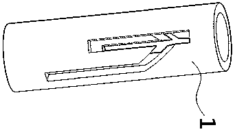
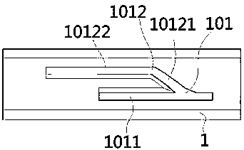
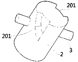
[0064] Such as Figure 1-4 As shown, an anti-miscontrol switch of this embodiment includes an anti-miscontrol device and a switch. The anti-miscontrol device includes a component tube (1), a passive part (2) and a limit rod (3). The component tube (1) is a tubular structure with a component track (101) arranged on the side wall. The passive part (2) is a cylindrical structure installed in the component tube (1) and capable of moving up and down and rotating. The passive member (2) is fixedly connected with the limit rod (3) or forms an integral structure. The limit rod (3) can limit movement along the component track (101).

[0065] The driven part (2) is provided with a chute (201) along the outer peripheral surface, the chute (201) opens at the end of the driven part (2), and the longitudinal section of the chute (201) is a wedge-shaped structure.

[0066] The switch includes a switch control part and a switch body, the component tube (1) is fixedly connected to the swit...

Embodiment 2

[0072] Such as Figure 5 As shown, the anti-mis-control switch of this embodiment is basically the same as the main body structure of the anti-mis-control switch described in Embodiment 1, the difference is that: the passive part (2) is provided with through holes or A limit rod connection hole (202) formed by a screw hole; the limit rod (3) can be detachably and fixedly connected with the passive part (2) through the limit rod connection hole (202).

Embodiment 3

[0074] An anti-miscontrol switch in this embodiment is basically the same as the main body structure of the anti-misoperation switch described in any one of Embodiments 1-2, the difference lies in: the switch control part and the passive part (2) An auxiliary elastic element is provided between them. The elastic element can be an elastic structure such as a spring, a shrapnel, or a spring pin.


PUM


Abstract

The present invention provides an anti-miscontrol switch. The anti-miscontrol switch comprises an anti-miscontrol device and a switch. The anti-miscontrol device comprises a component pipe, a passivecomponent and a limit bar; the component pipe is provided with an anti-misoperation track and a control track; and the passive component is fixedly connected with the limit bar. The switch comprisesa switch control part and a switch body; the component pipe is fixedly connected with the switch body; the switch control part is arranged below the passive component; and the passive component is provided with a wedge-shaped chute. In the natural state, the limit bar can always move up and down along the anti-misoperation track. The present invention also provides a socket. The socket comprises acontrol structure, and the control structure can be inserted into the chute to contact with the inclined surface portion of the chute, so that after the control structure is inserted into the anti-miscontrol device, under the pressing action of the control structure, the passive component always has the tendency of deflection; and when the limit bar moves down to the connection between the anti-misoperation track and the control track, the passive component rotates, and the limit bar is driven to enter the control track, can continue to move down to continue to squeeze the button switch, andfinally control the on and off of the switch.

Description

technical field [0001] The invention relates to the field of switch sockets, more specifically, to an anti-miscontrol switch, a modular socket box and an electric shock-proof socket box. Background technique [0002] With the development of modern industry, more and more electrical equipment is used in the industrial field, and switches are needed in many electrical equipment; especially in the field of high-voltage electricity, in order to prevent accidents caused by misoperation of switches, usually Supporting locks, protective covers or specific operating tools to increase the difficulty of operating the switch, so as to prevent misoperation of the switch. [0003] Simultaneously, along with the improvement of people's safety awareness of electricity use, safety sockets are becoming popular. In the prior art, switches are arranged on the surface of the socket and electronic switches are arranged inside the socket to increase the safety of electricity use. [0004] The in...

Claims


Application Information

Patent Timeline
Patent Type & Authority Applications(China)
IPC IPC(8): H01H9/22H01R13/502H01R13/70
CPCH01H9/22H01R13/502H01R13/701
Inventor 李利
Owner 马鞍山虹迈专业化设计有限公司
Learn More