
Filtering device capable of achieving automatic cleaning and clothing treating equipment

A technology for clothing processing equipment and filtering devices, which is applied to washing devices, household dryers, cleaning methods and utensils, etc., can solve problems such as condenser blockage, water tank pollution, limited condensed water, etc. Simple and efficient drying

Active Publication Date: 2019-05-14
QINGDAO HAIER WASHING ELECTRIC APPLIANCES CO LTD +1
View PDF9 Cites 7 Cited by
  • Summary
  • Abstract
  • Description
  • Claims
  • Application Information

AI Technical Summary

Problems solved by technology

[0004] It is time-consuming and laborious to manually disassemble the condenser for cleaning. If the user forgets to clean it, the condenser will be seriously blocked, which will affect the drying efficiency and drying effect. Repeated disassembly will affect the sealing between the condenser and the air duct, and the drying process will The leakage of water vapor will affect the air humidity of the surrounding environment of the dryer, and this solution needs to set an opening on the front panel of the dryer to install the condenser or the filter of the condenser, which will affect the overall front panel of the dryer. Exterior
[0005] The design of using the condensed water collected by the clothes dryer to flush the condenser does not require the user to manually disassemble the condenser, but the amount of condensed water in the water tank is limited, and the cleaned lint will be collected in the water tank again, which may cause drainage The blockage of the pump and the pipeline will cause the pollution of the water tank and affect the effect of the next cleaning. It does not have the ability of sustainable cleaning, and it cannot be cleaned at any time.

Method used


Image

  • Filtering device capable of achieving automatic cleaning and clothing treating equipment
  • Filtering device capable of achieving automatic cleaning and clothing treating equipment
  • Filtering device capable of achieving automatic cleaning and clothing treating equipment

Examples


Embodiment 1

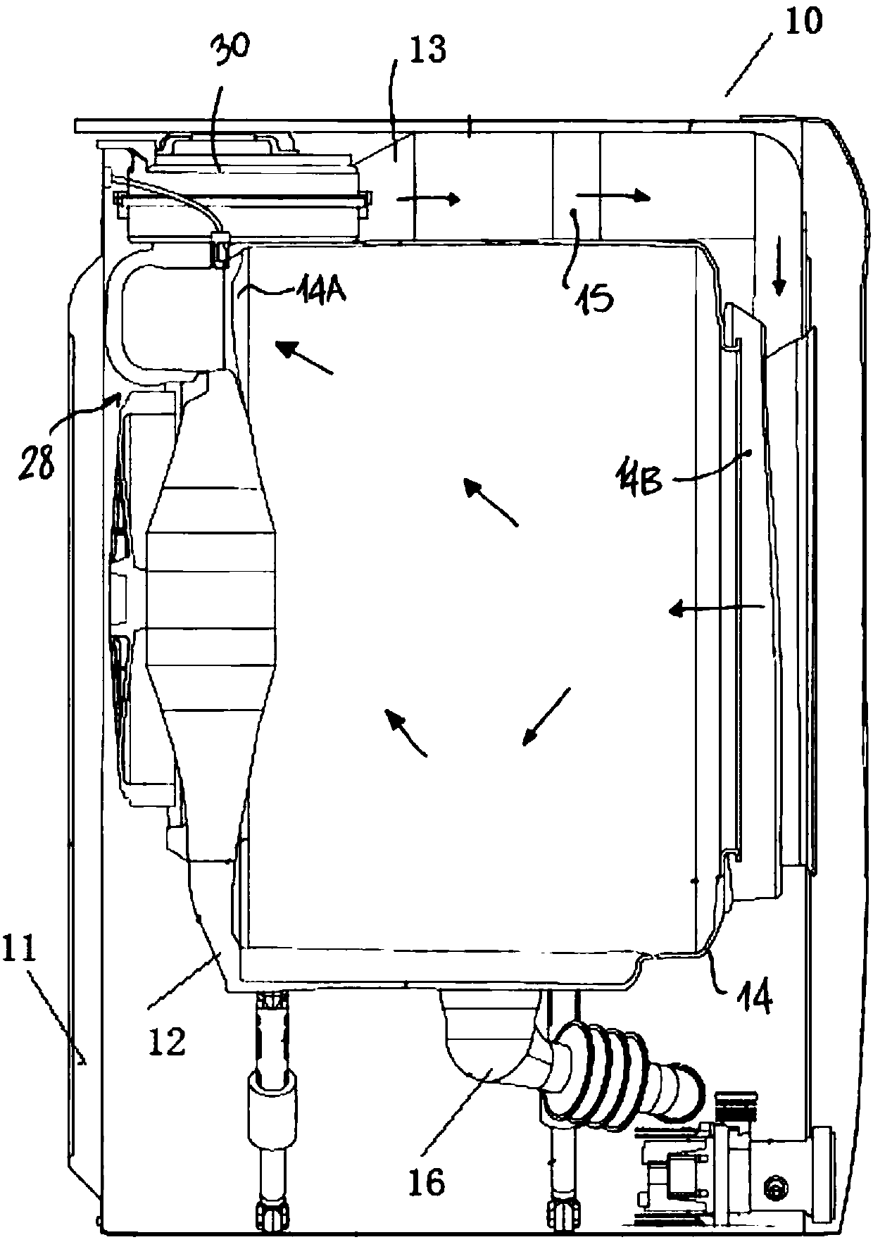
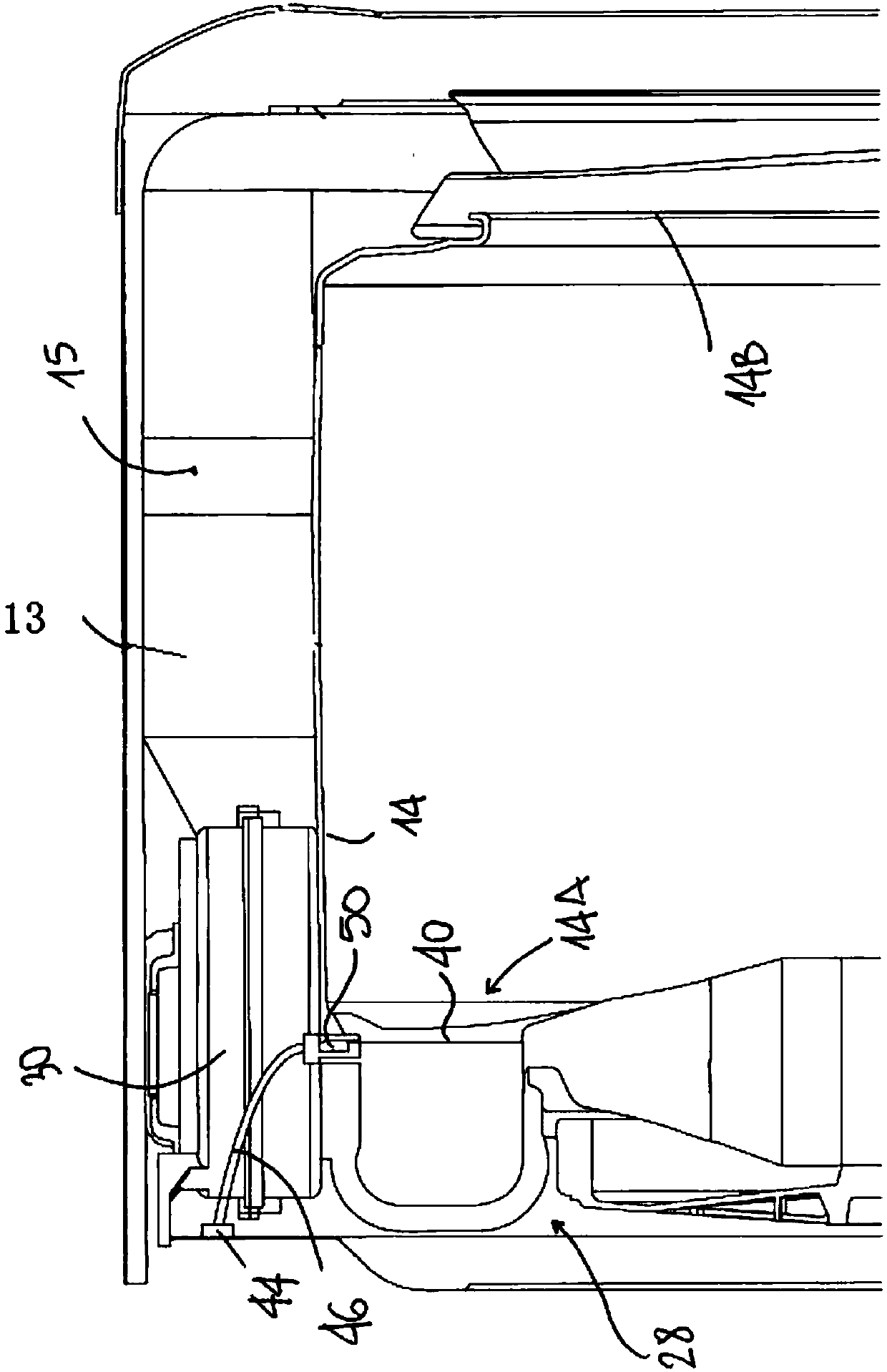
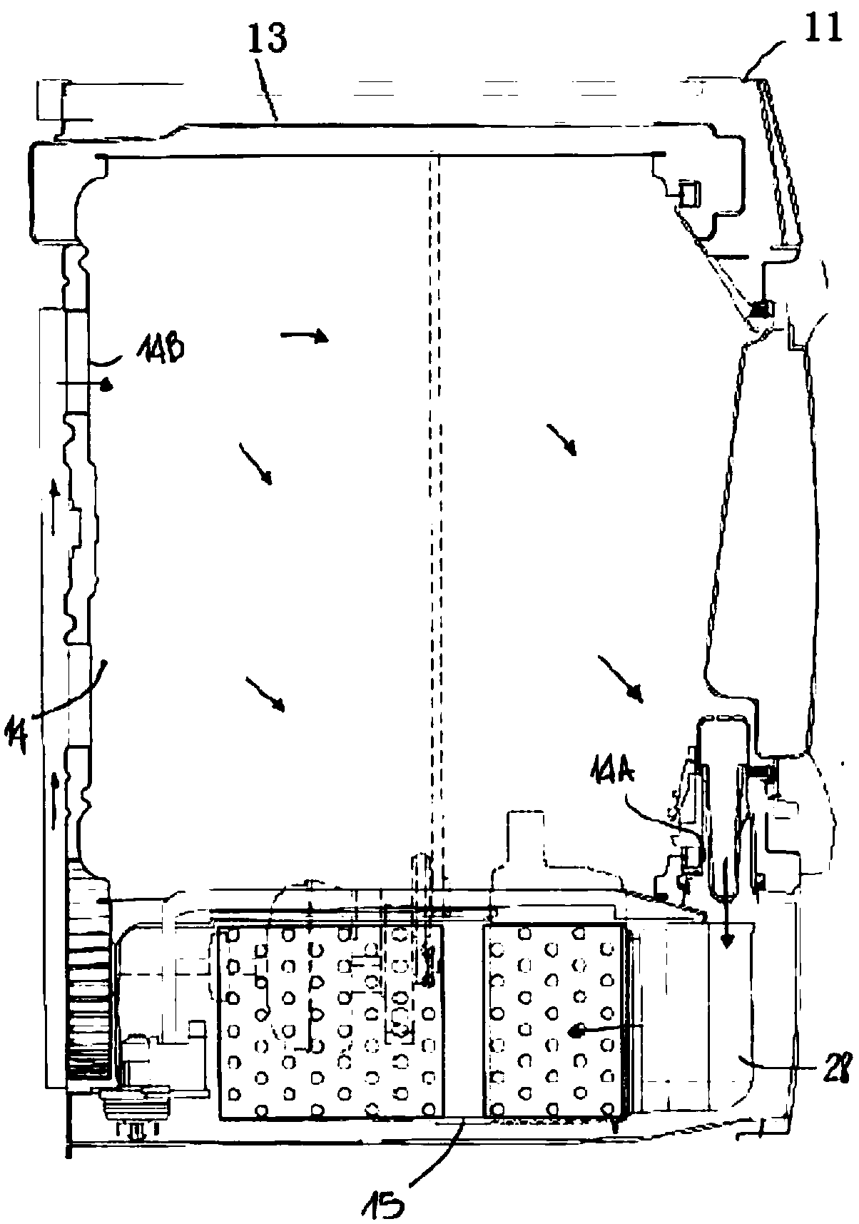
[0051] like Figure 1-7 As shown, the present embodiment provides a filter device 28 that can be cleaned automatically. The filter device 28 includes a tubular support structure 43, a filter structure and a cleaning structure. The inside of the tubular support structure 43 has a passage for gas circulation. 81. The filtering structure is inserted inwardly from the outer circumference of the tubular supporting structure 43 into the tubular supporting structure 43, so that the gas circulating in the channel 81 is filtered through the filtering structure, and the cleaning structure is arranged above the filtering structure, and is transported to the filtering structure The washing liquid flushes the filter structure.

[0052] The filter device 28 of this embodiment is assembled on the clothes treatment device 10 for drying the clothes at least once. The filter device 28 can be fixedly connected with the air circulation channel 13 of the clothes treatment device 10 as a separate p...

Embodiment 2

[0070] like Figure 4-7 As shown, this embodiment is a further limitation of Embodiment 1. The filter device 28 of this embodiment at least includes a first filter structure 40 and a second filter structure 60, both of which are respectively inserted into respective tubular support structures 43, and both The tubular support structure 43 is connected, the first filter structure 40 and the second filter structure 60 are arranged in parallel or at a certain angle, and the gas flows through the first filter structure 40 and the second filter structure 60 for filtration.

[0071] In order to enhance the filtering effect and prevent lint and lint from adhering to the condenser 30 with the airflow, at least two filtering structures are provided in this solution. The tubular support structures 43 of the first filter structure 40 and the second filter structure 60 can be directly fixed to each other, and the channels communicate with each other, or can be indirectly connected and fixe...

Embodiment 3

[0079] like Figure 4 As shown, the present embodiment is a further limitation of the second embodiment, the assembly support structure 80 is a horizontal linear pipeline, and the tubular support structures 43 of the first filter structure 40 and the second filter structure 60 are respectively arranged on the assembly support The two ends of the structure 80 are integrally formed or fixedly connected, and the filtering planes of the first filtering structure 40 and the second filtering structure 60 are arranged in parallel, and both are perpendicular to the central axis of the linear pipe.

[0080] During assembly, the first filter structure 40 is inserted into the first slot 83, the first cleaning structure 50 is fastened to the upper part of the first support frame 41, and then the body of the first cleaning structure 50, the first support frame 41 and the first insert The groove 83 is fixed by bolts. The second filter structure 60 is inserted into the second slot 84, the s...


PUM


Abstract

The invention discloses a filtering device capable of achieving automatic cleaning and clothing treating equipment. The filtering device includes a tubular supporting structure, a filtering structureand a cleaning structure, the tubular supporting structure is internally provided with a channel allowing gas to flow, the filtering structure is inserted into the tubular supporting structure from the periphery of the tubular supporting structure, and the gas flowing in the channel is filtered by the filtering structure; and the cleaning structure is arranged on the upper part of the filtering structure, and washing liquid is conveyed to the filtering structure to wash the filtering structure. The filtering device capable of achieving automatic cleaning does not need to be removed, on the original position, the washing liquid can be automatically fed to scour line scraps on the filtering structure, use burden of users can be reduced, the time and labor are saved, and the overall attractiveness of the clothing treating equipment is ensured; and meanwhile, the sufficient washing liquid and pressure can be provided for sustainable cleaning, and blocking is avoided.

Description

technical field [0001] The invention belongs to the field of washing machines or clothes dryers, and in particular relates to an automatic cleaning filter device and clothes processing equipment. Background technique [0002] In the process of drying clothes, especially when the clothes are in a dry state with a low moisture content, the fine fluff on the clothes will be stripped off by the circulating air in the cylinder, and then enter into the condenser of the dryer, although the fluff will be dried The primary filter at the mouth of the clothes machine is filtered, but the fine fluff will also pass through the primary filter to reach the condenser area and attach to the fins of the condenser. [0003] The existing condenser cleaning technology mainly has two aspects: first, manually remove the condenser and rinse it under the faucet; second, use the condensed water collected during the drying process of the clothes dryer to directly rinse the dry clothes machine condens...

Claims


Application Information

Patent Timeline
IPC IPC(8): D06F58/22D06F58/10B08B3/02
CPCB08B3/02D06F58/22
Inventor 李文伟邢本驸潘继辉张新华衣少磊蔡荣帅
Owner QINGDAO HAIER WASHING ELECTRIC APPLIANCES CO LTD
Learn More