Well drilling self-excited vibration and stick-slip vibration simulation experiment device

A technology for simulating experimental device and self-excited vibration, applied in drilling equipment, drilling measurement, earthwork drilling, etc., can solve the problems of inaccuracy, directness, inability to simulate stick-slip vibration, etc., to achieve high monitoring accuracy and good effect Effect

Active Publication Date: 2019-05-14
NORTHEASTERN UNIV
View PDF25 Cites 4 Cited by
  • Summary
  • Abstract
  • Description
  • Claims
  • Application Information

AI Technical Summary

Problems solved by technology

[0005] For the vibration simulation device of the drill string system in the prior art, there are generally the following deficiencies: 1. The drilling fluid type device cannot directly test the pressure value of the drill bit end, and only calculate the pressure of the drill bit end by the tension transmitted to the lug of the hydraulic cylinder , imprecise, not direct; 2. No drilling fluid device can not simulate the real cutting process of the drill bit, and can not simulate the self-excited vibration of the drill string; 3. It is impossible to directly test the torque and speed at the end of the drill bit and the input torque and speed at the top of the drill string 4. It cannot simulate the stick-slip vibration in the real cutting process

Method used


Image

  • Well drilling self-excited vibration and stick-slip vibration simulation experiment device
  • Well drilling self-excited vibration and stick-slip vibration simulation experiment device
  • Well drilling self-excited vibration and stick-slip vibration simulation experiment device

Examples


Embodiment Construction

[0041] The present invention will be further described in detail below in conjunction with the accompanying drawings, so that those skilled in the art can implement it with reference to the description.

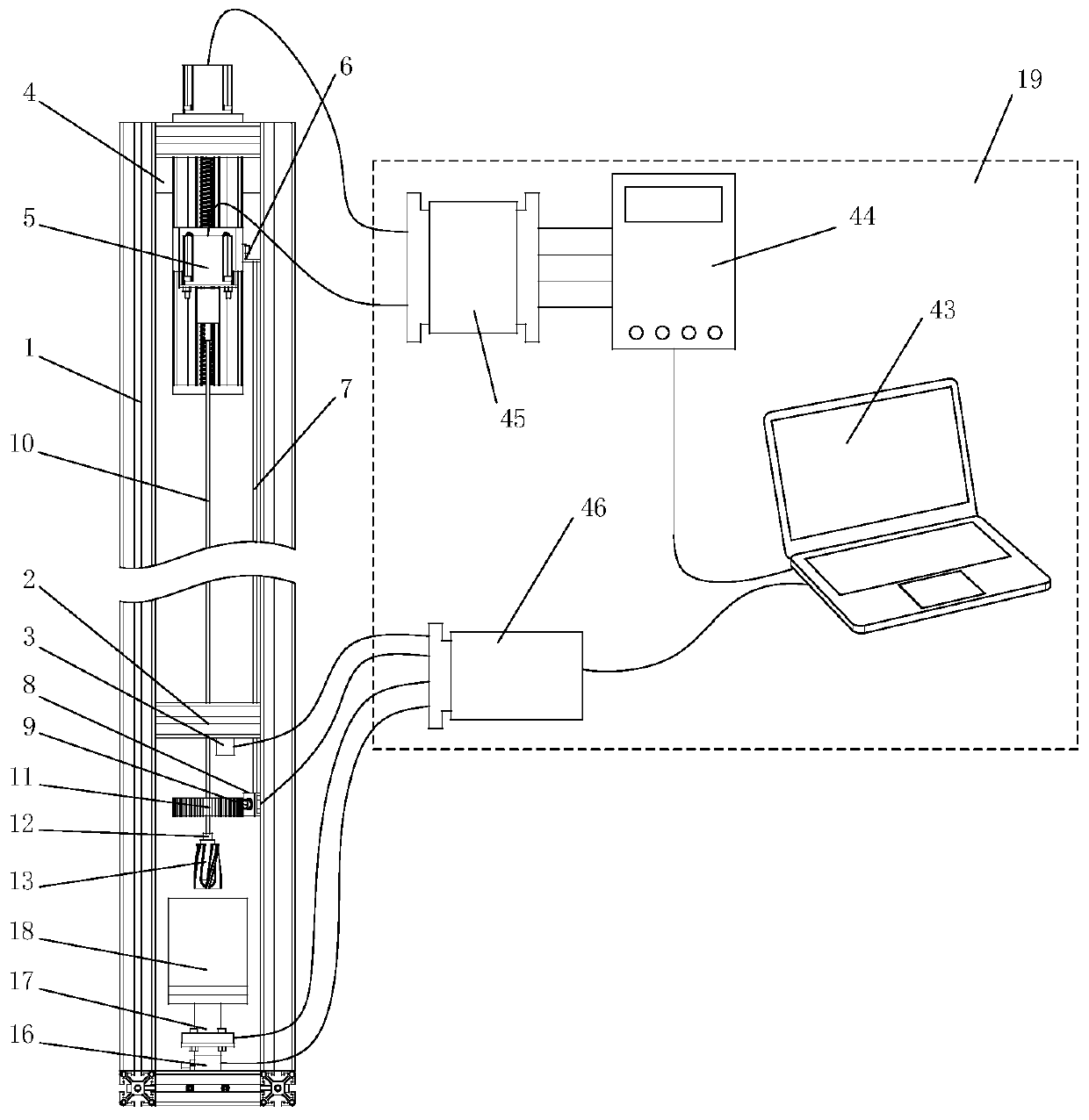
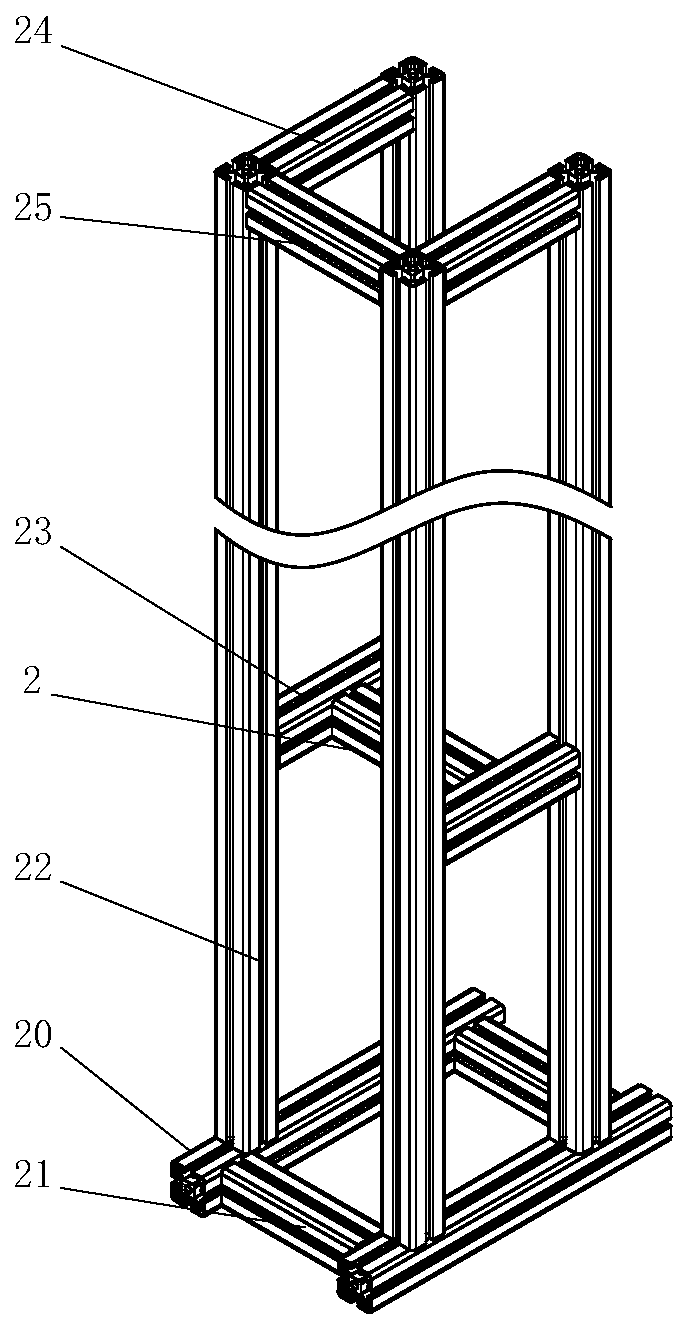
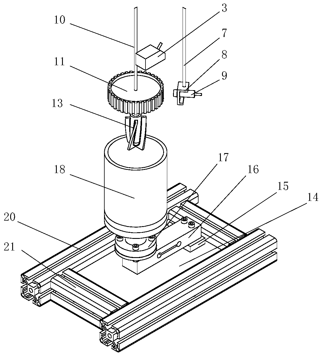
[0042] Such as Figure 1-7 As shown, a drilling self-excited vibration and stick-slip vibration simulation experiment device of the present invention includes: a frame assembly 1, a top drive assembly 5, a micro drill pipe 10, a micro drill bit 13, a simulated rock formation assembly 18, an optical code disc 11, Ultrasonic displacement sensor 3 , photoelectric sensor 9 , torque sensor 17 , pressure sensor 16 and data acquisition system 19 .

[0043] The top driving assembly 5 is installed on the top of the frame assembly 1 through the hanging plate 4 arranged on the upper rear side of the frame assembly 1 . The top drive assembly 5 is used to drive the micro drill rod 10 to move up and down and rotate. One end of the micro drill pipe 10 is connected to the top driving assem...


PUM


Abstract

The invention discloses a well drilling self-excited vibration and stick-slip vibration simulation experiment device. A stepping motor rotates to drive a sliding block and a servo motor to feed downwards; a drill bit downwards cuts a simulated rock stratum material in a barrel-shaped container; rotation speeds and torques of the stepping motor and the servo motor can be transmitted into a notebookcomputer through a motor driver and a motor controller. A pressure sensor, a torsion sensor, a photoelectric sensor and an ultrasonic displacement sensor which are installed on a bottom plate transmit cutting force, torsion, rotating speed and drilling speed of a drill bit to a notebook computer through a data acquisition card so as to simulate a real drilling working process, and reference basesare provided for analysis of self-excited vibration and stick-slip vibration of a drill stem through the data.

Description

technical field [0001] The invention belongs to the technical field of drilling, and relates to a drilling self-excited vibration and stick-slip vibration simulation experiment device. Background technique [0002] Drilling technology plays a vital role in the exploitation of mineral resources such as oil, natural gas and coal. The drilling process is a regenerative cutting process. When the drilling depth is shallow, the contact stress between the drill bit and the rock formation is small, and the vibration of the drill string is mainly due to the self-excited vibration caused by the regenerative cutting effect; as the drilling depth increases, the drill bit and the rock formation As the contact stress gradually increases, the friction between the drill bit and the rock increases, resulting in stick-slip vibration of the drill string system. Self-excited vibration can easily cause dynamic instability of the drill string system, while stick-slip vibration can easily lead to...

Claims


Application Information

Patent Timeline
Patent Type & Authority Applications(China)
IPC IPC(8): E21B47/00E21B47/06E21B45/00
Inventor 邓鹏飞李鹤张傲
Owner NORTHEASTERN UNIV
Why Eureka
Try Eureka