Intelligent and efficient self-priming pump

A self-priming pump and high-efficiency technology, which is applied in the field of intelligent and efficient self-priming pumps, can solve the problems of difficult to completely discharge the gas, affect the pump suction range, and long water filling time, so as to avoid no-load operation, prolong the service life, and liquid speed effect

Pending Publication Date: 2019-05-14
湘潭市红高科技有限公司
View PDF0 Cites 0 Cited by
  • Summary
  • Abstract
  • Description
  • Claims
  • Application Information

AI Technical Summary

Problems solved by technology

As the exhaust gas needs to be cycled for a long time, it is difficult to completely discharge the gas, which affects the suction of the pump, makes the water supply time long, the water pressure is unstable, and it is easy to generate noise.

Method used


Image

  • Intelligent and efficient self-priming pump
  • Intelligent and efficient self-priming pump
  • Intelligent and efficient self-priming pump

Examples


Embodiment 1

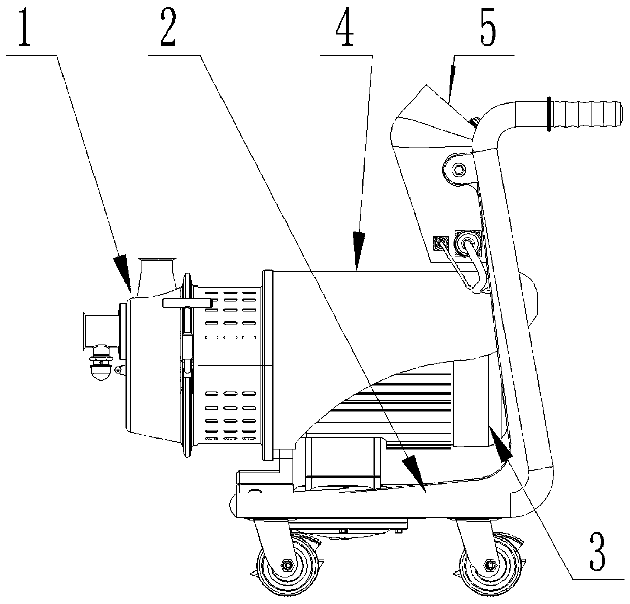
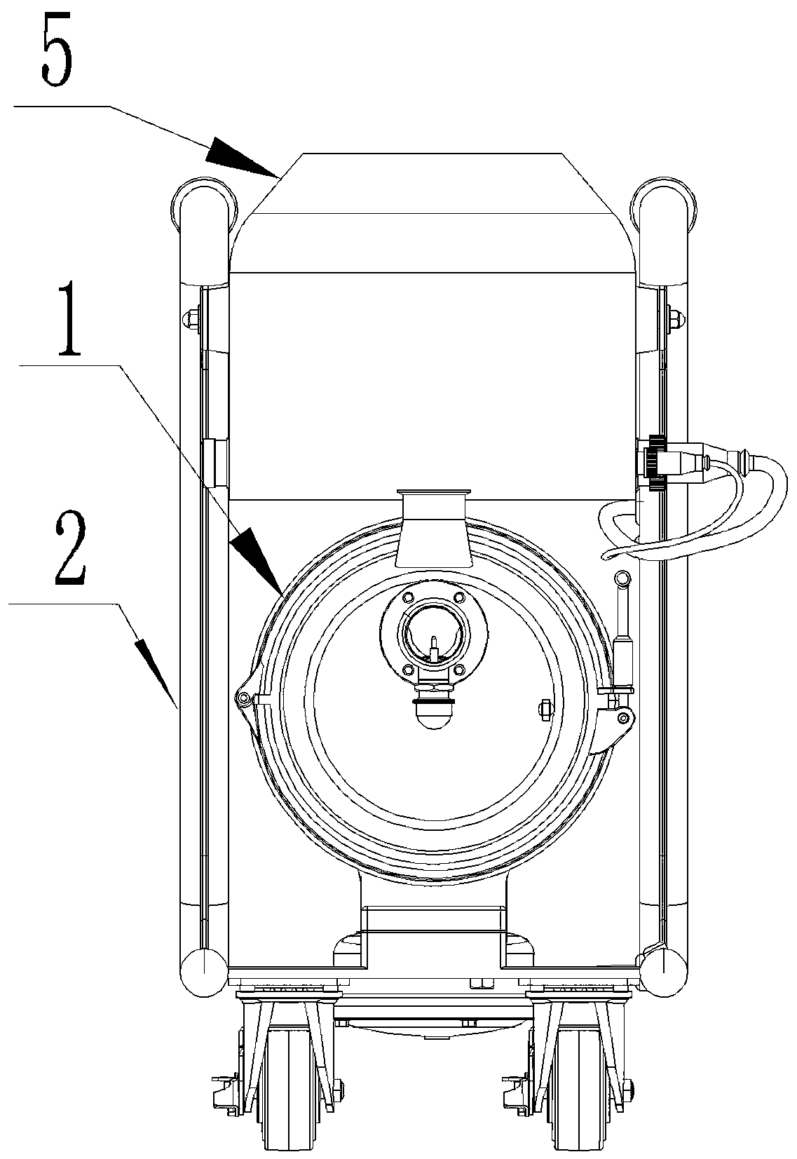
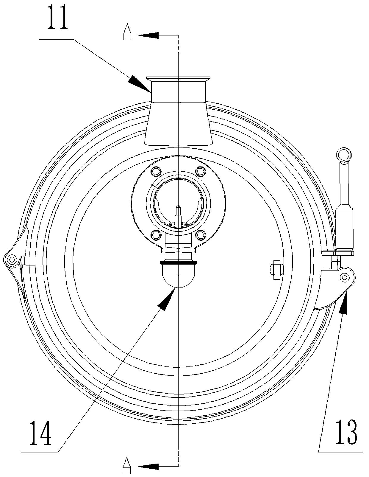
[0026] Embodiment 1, the present invention includes a pump body 1 and a motor 3 that are connected to each other. The pump body 1 includes a front pump body 11 and a rear pump body 12. A liquid sensor 14 is arranged on the liquid inlet seat 114 of the front pump body 11. The pump body 12 is provided with an isolation cavity 1251 and the throat cavity 119 in the front pump body 11 are sealed and connected with each other. The cavity 125 communicates with the throat cavity 119 , and the impeller 126 is arranged in the isolation cavity 125 , and the impeller 126 is set on the pump shaft 127 , and the pump shaft 127 is connected with the motor 3 . By setting the throat cavity and the isolation cavity, and adopting a sealed connection, the liquid inlet and the liquid outlet are isolated, and the motor starts to drive the impeller to rotate, which can quickly discharge the internal air, avoiding the internal circulation of gas and affecting the efficiency of the pump. Vacuum is form...

Embodiment 2

[0027] Embodiment 2, the upper part of the front pump casing 111 is provided with a liquid outlet 1110, the liquid inlet seat 114 is fixed on the outside of the front end of the front pump casing 111 through a screw, the liquid inlet seat gasket 115 is placed in the middle, and the throat cavity body 119 passes through the throat cavity flange 112 is sealed and fixed on the inside of the front end of the front pump casing 111, a throat cavity sealing gasket 116 is placed between the throat cavity flange 112 and the front pump casing 111, and a throat cavity sealing ring is placed between the throat cavity flange 112 and the flange bolts 117, the liquid inlet 118 communicates with the laryngeal cavity 113. refer to Figure 1 to Figure 10 , all the other are with embodiment 1.

Embodiment 3

[0028] Embodiment 3, one end of the pump seat 123 is set in the pump back seat 121, the other end is connected to the motor 3, the pump back seat 121 is set on the pump shaft 127, and the isolation chamber 1251 is fixed on the pump back seat 121 by a screw to form an isolation chamber 125, an isolation chamber sealing ring 124 is placed between the isolation chamber body 1251 and the pump back seat 121, the isolation chamber 125 is provided with an impeller 126 set on the pump shaft 127, and the end of the pump shaft 127 is provided with an impeller nut, and the impeller 126 is connected to the isolation chamber A front dynamic and static ring 15 is arranged between the chambers 1251 , a rear dynamic and static ring 128 is set between the impeller 126 and the pump back seat 121 and fitted on the pump shaft 127 , and a shield 129 is arranged outside the pump seat 123 . refer to Figure 1 to Figure 10 , and the rest are the same as the above-mentioned embodiment.


PUM


Abstract

The invention discloses an intelligent and efficient self-priming pump, and mainly solves the technical problems of low priming stroke, long water feeding time and unstable water pressure of an existing self-absorbing pump. The intelligent and efficient self-priming pump is characterized by comprising a pump body (1) and a motor (3) mutually connected, the pump body (1) comprises a front pump body(11) and a rear pump body (12), a liquid sensor (14) is arranged on a liquid inlet seat (114) of the front pump body (11), an isolation cavity body (1251) is formed in the rear pump body (12) and isin sealed and matched connection with a laryngeal cavity (119) in the front pump body (11), the other end of the isolation cavity body (1251) is matched with a pump rear seat (121) of the rear pump body (12) in a sealed mode to form an isolation cavity (125), the isolation cavity (125) communicates with the laryngeal cavity (119), an impeller (126) is arranged in the isolation cavity (125), the impeller (126) is mounted on a pump shaft (127) in a sleeving mode, and the pump shaft (127) is connected with the motor (3).

Description

technical field [0001] The invention relates to an intelligent high-efficiency self-priming pump. Background technique [0002] At present, the pump body of a traditional self-priming pump is composed of a suction chamber, a liquid storage chamber, a scroll chamber, a liquid return hole, and a gas-liquid separation chamber. The air is inhaled together and mixed completely in the impeller. Under the action of centrifugal force, the liquid entrains the gas and flows to the outer edge of the scroll, forming a white foam belt with a certain thickness and a high-speed rotating liquid ring on the outer edge of the impeller. The gas-liquid mixture enters the gas-liquid separation chamber through the diffusion tube. At this time, due to the sudden decrease of the flow rate, the lighter gas is separated from the gas-liquid mixture, and the gas continues to rise and discharge through the outlet of the pump body. The degassed liquid returns to the liquid storage chamber, and enters t...

Claims


Application Information

Patent Timeline
Patent Type & Authority Applications(China)
IPC IPC(8): F04D9/02F04D13/06F04D29/42F04D29/66F04D29/12F04D29/08F04D15/02
Inventor 张红勤
Owner 湘潭市红高科技有限公司
Why Eureka
Try Eureka