Particle light operation device based on annular core coaxial dual waveguide optical fiber

A ring-core, dual-waveguide technology, applied in the direction of optical waveguide light guide, multi-layer core/cladding optical fiber, cladding optical fiber, etc., can solve the problems of low flexibility and difficult probe application

Inactive Publication Date: 2019-05-14
GUILIN UNIV OF ELECTRONIC TECH
View PDF10 Cites 6 Cited by
  • Summary
  • Abstract
  • Description
  • Claims
  • Application Information

AI Technical Summary

Problems solved by technology

Although the system can achieve stable three-dimensional capture and rotation of particles, the system requires expensive and large spatial optical devices such as spatial light modulators, and its flexibility is not high, making it difficult to implement probe applications
Therefore, the researchers used the few-mode optical fiber tapered fiber-end probe to realize the three-dimensional capture and direction control of yeast cells (Jounal of Lightwave Technol, 2014, 32(6):1098-103), but this system cannot realize the Stable rotation function
In addition, Chen et al. also used the optical fiber LP21 mode to realize the rotation operation of biological cells (Journal of Optics, 2014, 16(12): 125302), but this system cannot form a stable three-dimensional capture of cells

Method used


Image

  • Particle light operation device based on annular core coaxial dual waveguide optical fiber
  • Particle light operation device based on annular core coaxial dual waveguide optical fiber
  • Particle light operation device based on annular core coaxial dual waveguide optical fiber

Examples


Embodiment Construction

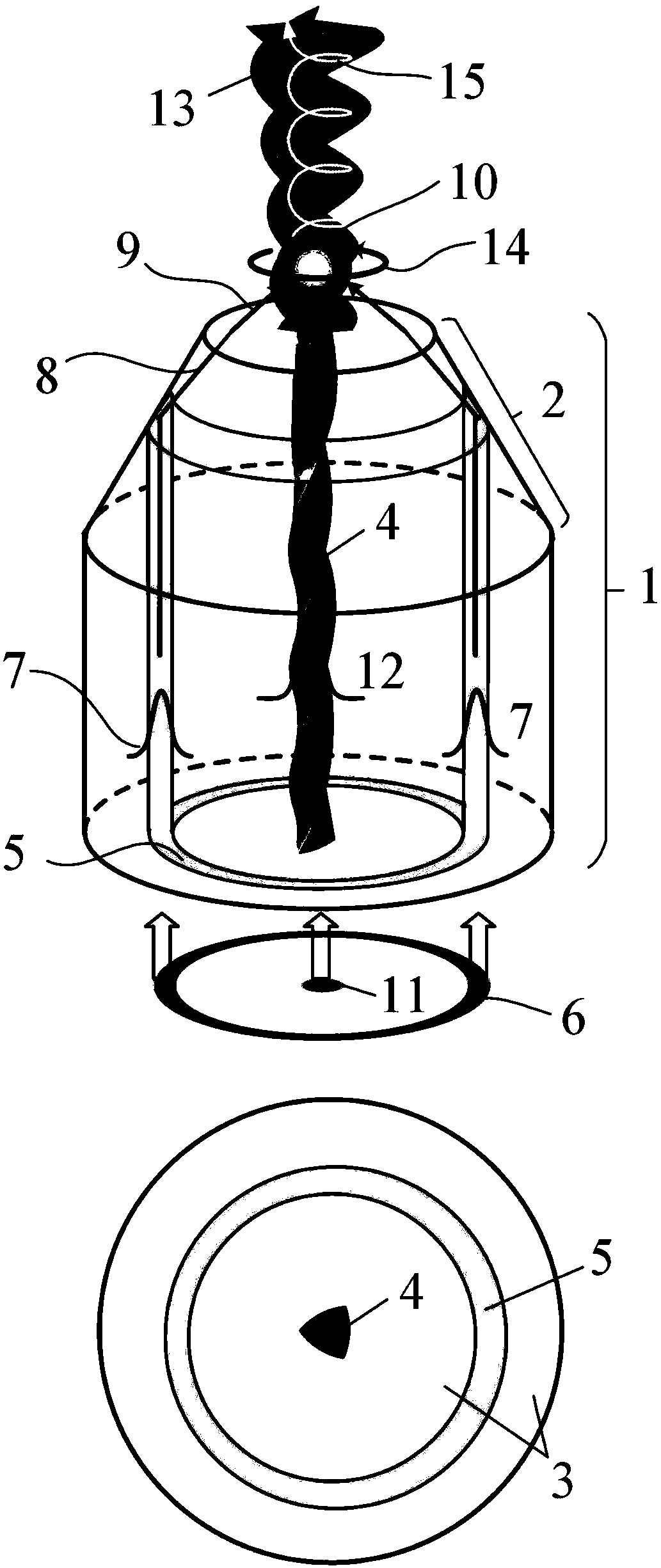
[0021] The present invention is described in more detail below in conjunction with accompanying drawing example:

[0022] combine Figure 1-Figure 3 , the embodiment of the present invention has a ring-core coaxial dual-waveguide optical fiber 1, and the fiber end of the fiber is ground to form a truncated cone 2 at the fiber end; The core 4 and the annular core 5 , the central helical core 4 and the annular core 5 are located in the center of the cladding 3 . The functional implementation of the device is like this (take the ring-core coaxial double waveguide with right-handed triangular central helical core as an example, such as figure 1 shown): On the one hand, when the ring light 6 is input to the ring core coaxial dual waveguide fiber 1, the ring core guided mode 7 will be excited in the ring core 5, and the cladding of the fiber end frustum 2 and the external medium At the interface of , the annular core guided mode 7 undergoes total internal reflection, and the refl...


PUM


Abstract

The invention provides a particle light operation device based on an annular core coaxial dual waveguide optical fiber. The particle light operation device is characterized by mainly consisting of a segment of annular core coaxial dual waveguide optical fiber 1, wherein a fiber end of the optical fiber is ground to form a fiber end cone frustum 2; the annular core coaxial dual waveguide optical fiber 1 comprises an envelope 3, a non-circular central helical fiber core 4 and an annular fiber core 5; the central helical fiber core 4 and the annular fiber core 5 are located in the center of the envelope 3; and the optical fiber can be prepared by rotating and drawing, or drawing as well as hot melting and twisting. On one hand, the particle light operation device can emit a strong focusing annular light field 9 from the fiber end of the annular core coaxial dual waveguide optical fiber to realize stable three-dimensional capture for particles 10 nearby a focusing point outside the fiber end, and realize positioning and axis-fixing functions for the particles 10. On the other hand, axis-fixed rotation 14 and rotary launch 15 of the particles 10 can be realized by controlling the energymagnitude of a phase vortex beam 13 emitted from the central helical fiber core. The particle light operation device can be applied to optical operation of small particles such as microfluid chips, cells or medicinal particles as well as application of optical fiber integrated devices.

Description

(1) Technical field [0001] The invention relates to a particle light manipulation device based on a ring-core coaxial dual-waveguide optical fiber, which can be used for light manipulation of tiny particles such as microfluidic chips, cells or drug particles, and the application of optical fiber integrated devices, etc., and belongs to the field of optical fiber technology. (2) Background technology [0002] As we all know, electromagnetic waves transmit not only energy but also momentum, which is a unique property of translational motion of all objects. When the momentum of electromagnetic waves is absorbed or scattered by other objects, "radiation pressure" will be formed, thereby forming mechanical pressure on the object . Likewise, light waves have angular momentum, a property of all rotational motion. The angular momentum of light wave can be decomposed into spin angular momentum and orbital angular momentum on the optical axis. What is special is that the light wave ...

Claims


Application Information

Patent Timeline
Patent Type & Authority Applications(China)
IPC IPC(8): G02B6/02G02B6/036G21K1/00C03B37/027
Inventor 苑立波邓洪昌
Owner GUILIN UNIV OF ELECTRONIC TECH
Why Eureka
Try Eureka