Light spot emission device and method for detecting geometric light spot

A launch device and spot technology, applied in the field of spot positioning, can solve the problems of limited working range of virtual walls, inability to cover large scene areas, insufficient intelligence and comprehensive planning, etc., to improve the accuracy of spot detection, improve the accuracy of self-positioning, The effect of improving the accuracy of spot positioning

Inactive Publication Date: 2019-05-14
JOYOUNG CO LTD
View PDF5 Cites 12 Cited by
  • Summary
  • Abstract
  • Description
  • Claims
  • Application Information

AI Technical Summary

Problems solved by technology

[0003] The traditional virtual wall has a limited working range and cannot cover a large scene area; a special detection device needs to be installed inside the sweeping robot to identify the virtual wall, and its information can only be available after it needs to be accurately aligned

Method used


Image

  • Light spot emission device and method for detecting geometric light spot
  • Light spot emission device and method for detecting geometric light spot
  • Light spot emission device and method for detecting geometric light spot

Examples


Embodiment 1

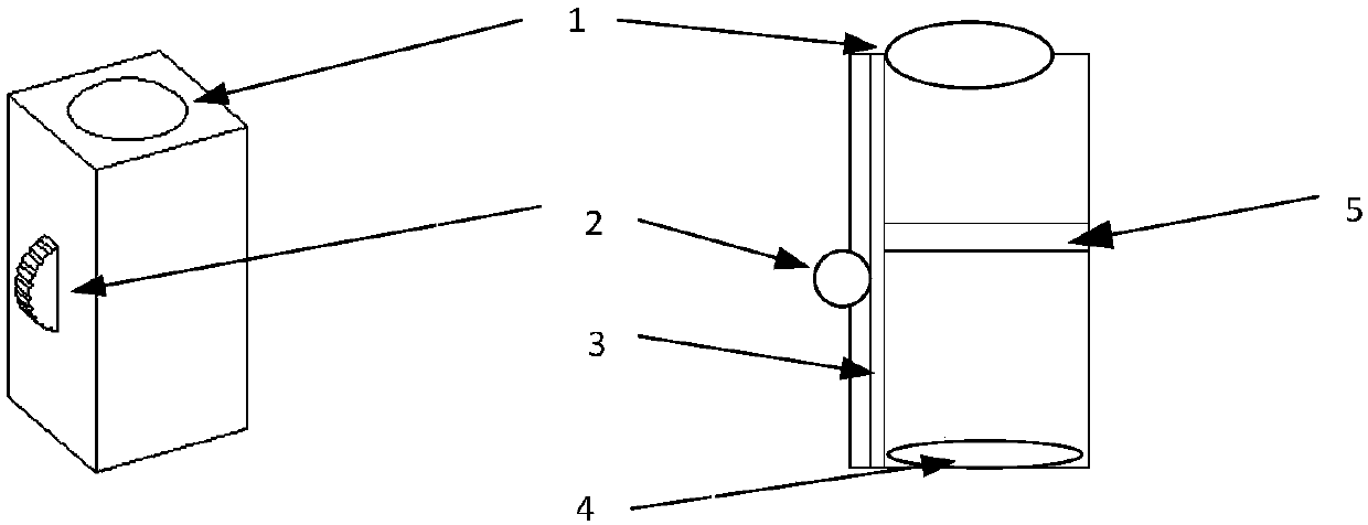
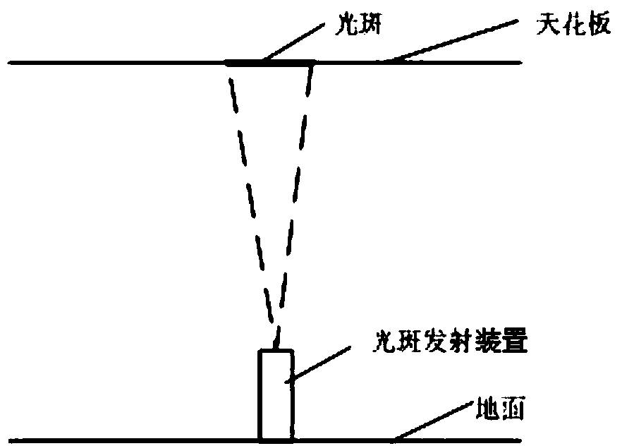
[0119] The light spot detection method described in this embodiment is as follows: the body of the sweeper has a camera module. During the movement of the sweeper, the camera module is turned on to continuously collect images on the ceiling (corresponding to Figure 14 in step 201). After the image is preprocessed, the original image can be converted into a clear camera video grayscale frame, thereby reducing the interference of image distortion and color change on the later detection algorithm (corresponding to Figure 14 in step 202). Afterwards, the grayscale frame stream after distortion correction is divided into two synchronously, and respectively enter into the global image positioning stitching (corresponding to Figure 14 Steps 203-206) and local spot detection. The local spot detection method identifies the corrected spot and marks its position in the frame (corresponding to Figure 14 Steps 207-209 in the middle); then map the identified light spots to the global...


PUM


Abstract

The invention puts forward a light spot emission device and a method for detecting a geometric light spot. The light spot emission device comprises a shell, a lens, a light spot size regulator, a light spot shape sheet, a regulation guide rail and a light source, wherein the lens, the light spot size regulator, the light spot shape sheet, the regulation guide rail and the light source are arrangedin the shell; after light emitted from the light source is projected to the light spot shape sheet, the light is amplified through the lens to form the geometric light spot of which the shape corresponds to the shape of the light spot; the regulation guide rail is arranged along a light spot spreading direction; and the light spot size regulator regulates the light spot shape sheet and/ or lightsource to move along the guide rail to regulate the size of the geometric light spot. Through one light spot emission device or the combination of a plurality of light spot emission devices, various virtual wall modes are realized. By use of the device, the problem of light spot detection in a visual virtual wall positioning process is solved, and light spot detection accuracy can be improved.

Description

technical field [0001] The invention relates to the field of spot positioning, in particular to a spot emitting device and a method for detecting geometric spots. Background technique [0002] Smart home is increasingly becoming a way of life for young people, and robots (such as sweeping robots) can enter the home, freeing people from daily housework. The current navigation of sweeping robots is mainly based on random collision, inertial navigation and laser navigation. The cleaning efficiency of random collision and inertial navigation is low; the cost of laser navigation is high, and the laser head wears out quickly, so it is difficult to guarantee long-term work. When the sweeping robot is unmanned, automatic cleaning in a certain area may enter some areas that users do not want the sweeping robot to enter, such as the area where children's toys are piled up. After entering, the sweeping robot may remove some small parts of the toys. Inhale the dust box; another exampl...

Claims


Application Information

Patent Timeline
IPC IPC(8): G02B27/09G02B27/48G01C21/20
Inventor 朱泽春余杰
Owner JOYOUNG CO LTD
Why Eureka
Try Eureka