Visual calibration method and device and robot controller

A calibration method and robot technology, applied in the fields of instruments, image data processing, computing, etc., can solve the problems of lack of visual calibration at the end of the robotic arm, cumbersome visual calibration, etc., and achieve a more humanized effect of visual calibration.

Inactive Publication Date: 2019-05-14
SHENZHEN YUEJIANG TECH CO LTD
View PDF6 Cites 8 Cited by
  • Summary
  • Abstract
  • Description
  • Claims
  • Application Information

AI Technical Summary

Problems solved by technology

[0005] The embodiment of the present invention aims to provide a visual calibration method, device and robot controller, which solves the technical problem of lack of visual calibration at the end of the existing mechanical arm or too cumbersome visual calibration, and realizes that the position of the mechanical arm changes without using Re-calibration to make the visual calibration at the end of the robotic arm more humanized and intelligent

Method used


Image

  • Visual calibration method and device and robot controller
  • Visual calibration method and device and robot controller
  • Visual calibration method and device and robot controller

Examples


Embodiment 1

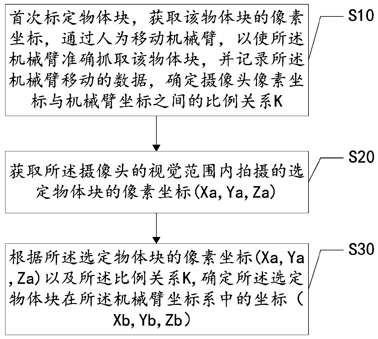
[0045] see figure 1 , figure 1 It is a schematic flowchart of a visual calibration method provided by an embodiment of the present invention;

[0046] Such as figure 1 As shown, the method is applied to a robot, such as a grabbing robot, wherein the robot is provided with a robot arm and a robot controller, the robot arm is connected to the robot controller, and the robot controller is used to control the robot arm Operation, the mechanical arm is used to grab or release objects, at least one camera is installed at the end of the mechanical arm, each of the cameras is connected to the robot controller, the camera can be a high-definition camera, and the camera For acquiring image information of objects within the visual range, and sending the image information to a robot controller, the method includes:

[0047] Step S10: calibrate the object block for the first time, obtain the pixel coordinates of the object block, manually move the mechanical arm so that the mechanical a...

Embodiment 2

[0061] see Figure 5 , Figure 5 A schematic structural diagram of a visual calibration device provided in an embodiment of the present invention, the visual calibration device can be applied to a robot, the robot includes a robot controller and a mechanical arm, and at least one camera is installed at the end of the mechanical arm, such as Figure 5 As shown, the visual marking device 100 includes:

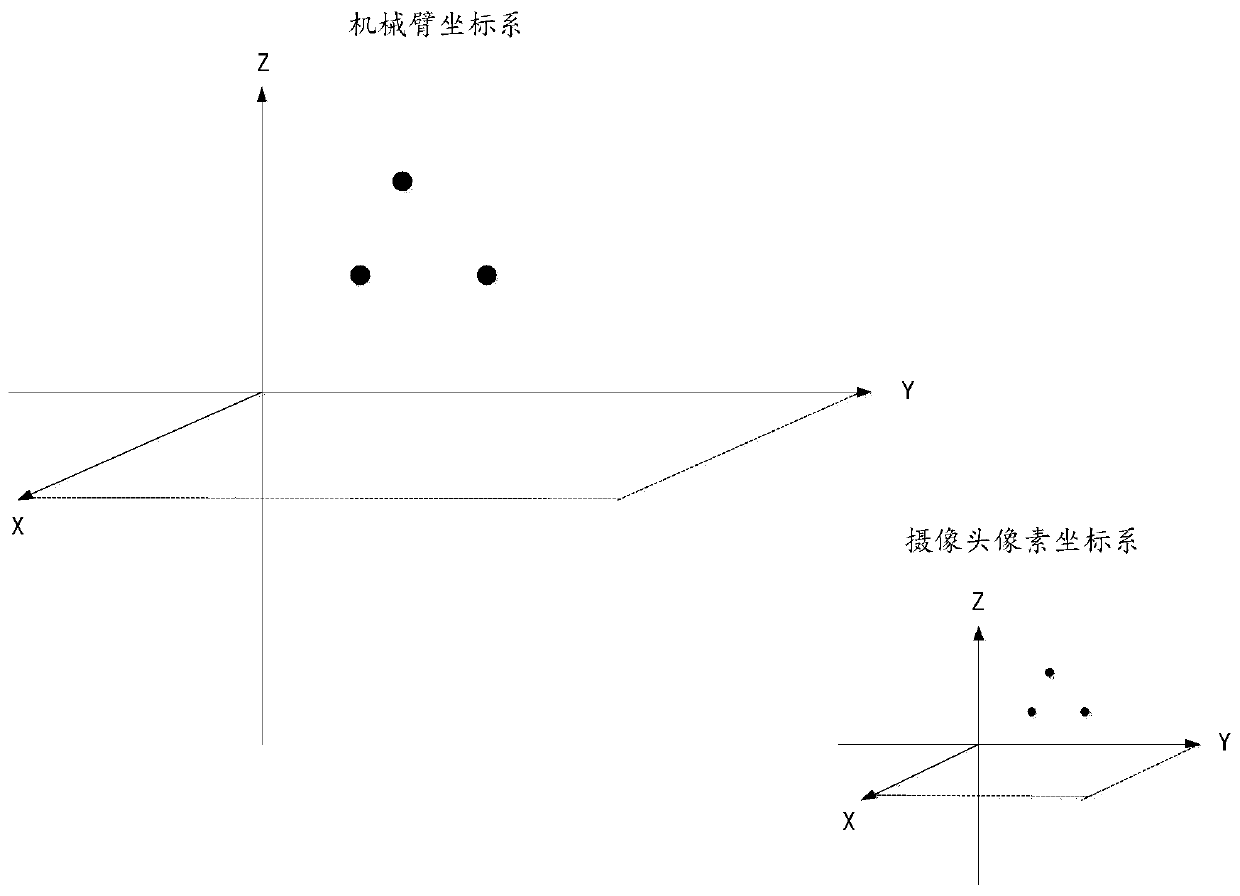
[0062] The proportional relationship unit 10 is used to calibrate the object block for the first time, obtain the pixel coordinates of the object block, manually move the mechanical arm so that the mechanical arm can accurately grasp the object block, and record the movement data of the mechanical arm to determine The proportional relationship K between the pixel coordinates of the camera and the coordinates of the manipulator;

[0063] A pixel coordinate acquiring unit 20, configured to acquire pixel coordinates (Xa, Ya, Za) of a selected object block captured within the visua...


PUM


Abstract

The embodiment of the invention relates to the field of robot control, and discloses a visual calibration method and device and a robot controller. The visual calibration method comprises: an object block is calibrated for the first time, pixel coordinates of the object block are obtained, the mechanical arm is moved manually to accurately grab the object block, moving data of the mechanical arm are recorded, and the proportional relation between the pixel coordinates of a camera and the coordinates of the mechanical arm is determined; obtaining pixel coordinates of a selected object block shot in the visual range of the camera; and determining the coordinates of the selected object block in the mechanical arm coordinate system according to the pixel coordinates of the selected object block and the proportional relation. By means of the mode, the technical problem that visual calibration is lacked at the tail end of an existing mechanical arm or visual calibration is too complex can besolved, and more user-friendly and intelligent visual calibration of the tail end of the mechanical arm is achieved.

Description

technical field [0001] The invention relates to the field of robot control, in particular to a visual calibration method, device and robot controller. Background technique [0002] Robots, also known as automatic control machines, include all machinery that simulates human behavior or thinking and simulates other creatures. In modern industry, a robot refers to a man-made machine device that can perform tasks automatically to replace or assist human work. The robot's mechanical arm plays an irreplaceable role in object grasping, so the robot's vision system is particularly important. [0003] At present, the lack of visual calibration at the end of the robotic arm leads to large errors in the process of grasping objects, resulting in grasping failure. The position of the robotic arm has changed and needs to be calibrated again. [0004] In the process of implementing the embodiments of the present invention, the inventors found that the related technologies have at least ...

Claims


Application Information

Patent Timeline
Patent Type & Authority Applications(China)
IPC IPC(8): G06T7/70
Inventor 刘祥庄飞飞雷德华刘志立
Owner SHENZHEN YUEJIANG TECH CO LTD
Why Eureka
Try Eureka