Detection circuit and display substrate

A technology for detecting circuits and display areas, applied to static indicators, instruments, etc., can solve problems such as poor display

Active Publication Date: 2019-05-14
HKC CORP LTD
6 Cites 5 Cited by

AI-Extracted Technical Summary

Problems solved by technology

[0004] The invention provides a detection circuit and a display sub...

Method used

[0066] To sum up, the embodiment of the present invention provides a detection circuit and a display substrate, the detection circuit includes a trigger unit 100 and a switch unit 200. The first input end of the trigger unit 100 is electrically connected to the test machine, the second input end of the trigger unit 100 is electrically connected to the output end of the trigger unit 100, the third input end of the trigger unit 100 is grounded, It is used for receiving a test signal provided by the test machine, and generating a switch control signal according to the test signal and the voltage signal at the second input terminal of the trigger unit 100 . The first input terminal of the switch unit 200 is electrically connected to the second input terminal of the trigger unit 100 and the output terminal of the trigger unit 100, and the second input terminal of the switch unit 200 is electrically connected to the signal bus, so T...

Abstract

The embodiment of the invention provides a detection circuit and a display substrate. The detection circuit comprises a trigger unit and a switch unit. the first input end of the trigger unit is electrically connected with the test machine; The second input end of the trigger unit is electrically connected with the output end of the trigger unit, and the third input end of the trigger unit is grounded and used for receiving a test signal provided by the test machine and generating a switch control signal according to the test signal and a voltage signal of the second input end of the trigger unit. The first input end of the switch unit is electrically connected with the second input end of the trigger unit and the output end of the trigger unit. The second input end of the switch unit is electrically connected with a signal bus, and the output end of the switch unit is electrically connected with a display area and used for receiving the switch control signal and disconnecting the signal bus from the display area after detection is completed according to the switch control signal.

Application Domain

Static indicating devices

Technology Topic

ElectricityVoltage +1

Image

  • Detection circuit and display substrate
  • Detection circuit and display substrate
  • Detection circuit and display substrate

Examples

  • Experimental program(1)

Example Embodiment

[0032] In order to make the above-mentioned objects, features and advantages of the present invention more obvious and understandable, the specific embodiments of the present invention will be described in detail below with reference to the accompanying drawings. In the following description, many specific details are explained in order to fully understand the present invention. However, the present invention can be implemented in many other ways different from those described herein, and those skilled in the art can make similar improvements without departing from the connotation of the present invention. Therefore, the present invention is not limited by the specific implementation disclosed below.
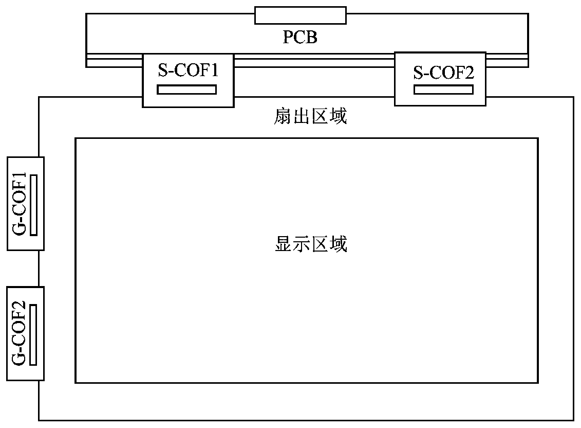
[0033] Such as figure 1 As shown, TFT-LCD (Thin Film Transistor Liquid Crystal Display) is one of the main types of current flat panel displays, and has become an important display platform in modern IT and video products. The main driving principle of TFT-LCD, the system motherboard connects the R/G/B pixel signal, control signal and power supply to the connector on the PCB through the signal line, and passes through the TCON (Timing Controller) IC on the PCB. (Integrated Circuit, integrated circuit) after processing, through the PCB board, through the S-COF (Source-Chip on Film, source driver chip) and G-COF (Gate-Chip on Film gate driver chip) connected to the display area, So that the LCD obtains the required power and signals.
[0034] In the existing design, the gate side fan-out area is designed as figure 2 Shown. In order to ensure product quality, before bonding the PCB to the S-COF and G-COF, it is necessary to inspect the image quality of the display panel. In the current detection scheme, three signal buses, R, G, and B are set on the Gate side, among which Channel N is connected to R, Channel N+1 is connected to G, and Channel N+2 is connected to B, reciprocating in turn. Pad N, Pad N+1, Pad N+2 are the corresponding bonding pads when G-COF is actually bonded. When the G-COF is not attached, the signal can be injected to the display panel through the three signal buses R, G, and B for image detection. After the picture detection is completed, the external irrigation circuit is cut off by laser to avoid the influence of the R/G/B bus on the display after the G-COF is attached. However, two adjacent leads may be short-circuited at the cut section. After the short-circuited display panel is energized, sintering will occur, destroying the internal lead structure of the panel or even the package, and causing defects in the panel.
[0035] In view of the above-mentioned problems, an embodiment of the present invention provides a detection circuit. See image 3 The detection circuit includes a trigger unit 100 and a switch unit 200.
[0036] The first input terminal of the trigger unit 100 is electrically connected to a testing machine, the second input terminal of the trigger unit 100 is electrically connected to the output terminal of the trigger unit 100, and the third input terminal of the trigger unit 100 is grounded. It is used to receive the test signal provided by the test machine, and generate a switch control signal according to the test signal and the voltage signal of the second input terminal of the trigger unit 100.
[0037] The first input terminal of the switch unit 200 is electrically connected with the second input terminal of the trigger unit 100 and the output terminal of the trigger unit 100, and the second input terminal of the switch unit 200 is electrically connected with the signal bus. The output terminal of the switch unit 200 is electrically connected to the display area, and is used to receive the switch control signal, and disconnect the connection between the signal bus and the display area after the detection is completed according to the switch control signal.
[0038] It can be understood that the trigger unit 100 generates a switch control signal according to the test signal and the voltage signal at the second input terminal of the trigger unit 100, so that the switch unit 200 is turned off after the detection is completed according to the switch control signal. The connection between the signal bus and the display area. After the PCB is bonded to the S-COF and G-COF, when the driving signal is provided to the display area through the S-COF and G-COF, the driving signal will not be poured back onto the signal bus. Therefore, when image detection is performed by the detection circuit provided in this embodiment, there is no need to cut the connection between the signal bus and the display area by laser laser, which avoids possible problems caused by laser cutting and improves product quality.
[0039] In one of the embodiments, the detection circuit further includes a comparison unit 300. See Figure 4 , The input terminal of the comparison unit 300 is electrically connected to the test machine, and the output terminal of the comparison unit 300 is electrically connected to the first input terminal of the trigger unit 100 for receiving the test signal, and When the voltage of the test signal is greater than the threshold voltage, the test signal is output through the output terminal of the comparison unit 300.
[0040] In this embodiment, in the image detection stage, the test machine provides a high-level test signal to the input terminal of the comparison unit 300. Generally speaking, the test signal is 1.2-2 of the threshold voltage. Therefore, when the test signal is at a high level, the comparison unit 300 outputs the test signal to the trigger unit 100, so that the trigger unit 100 triggers according to the test signal to generate a high-level switch The control signal is used to turn on the switch unit 200 according to the high-level switch control signal generated at this stage, and provide the signal on the signal bus to the display area. Moreover, after the screen test is completed, the test machine again outputs a high-level test signal, and the trigger unit 100 generates a low-level control signal according to the high-level test signal, so that the switch unit 200 According to the low-level switch control signal, the connection between the signal bus and the display area is disconnected, so there is no need to disconnect the signal bus from the display area by laser cutting, which avoids possible laser cutting. Bad display problem.
[0041] In one of the embodiments, the comparison unit 300 includes a first diode D1, the cathode of the first diode D1 is electrically connected to the testing machine, and the anode of the first diode D1 is electrically connected to the test machine. The first input terminal of the trigger unit 100 is electrically connected.
[0042] It can be understood that the diode has a unidirectional conduction function, and when the voltage at the cathode of the diode is less than or equal to the threshold voltage of the diode, the diode is turned off. When the voltage at the cathode of the diode is greater than the threshold voltage of the diode, the diode is reversely broken down and turns from the off state to the on state. In this embodiment, the threshold voltage is the threshold voltage of the reverse breakdown voltage of the first diode D1, and the first diode D1 is a reverse breakdown recoverable diode. In the image detection stage, the first diode D1 is reversely broken down by the high-level test signal provided by the machine, and the high-level test signal is provided to the trigger unit 100, so that the trigger unit 100 generates a high-level switch control signal according to the high-level test signal and the low-level signal at the second input terminal of the trigger unit 100, so that the switch unit 200 is turned on according to the high-level switch control signal , Provide the signal on the signal bus to the display area for screen detection. After the test is completed, the machine provides the test signal again, the first diode D1 breaks down the test signal again, and the trigger unit 100 responds to the high-level signal at its second input terminal and The test signal generates a low-level switch control signal, so that the switch unit 200 disconnects the connection between the signal bus and the display area according to the low-level switch control signal.
[0043] In one of the embodiments, the trigger unit 100 includes a first resistor R, a flip-flop D2, an inverter D3, and a second resistor R2.
[0044] The first end of the first resistor R is electrically connected to the anode of the first diode D1, and the second end of the first resistor R is grounded.
[0045] The set terminal of the trigger D2 is electrically connected to the first input terminal of the switch unit 200, and the trigger terminal of the trigger D2 is connected to the anode of the first diode D1 and the first resistor R The first end is electrically connected.
[0046] The input terminal of the inverter D3 is electrically connected to the forward output terminal of the flip-flop D2, and the output terminal of the inverter D3 is connected to the first input terminal of the switch unit 200 and the flip-flop D2. The setting terminal is electrically connected.
[0047] The first end of the second resistor R2 is electrically connected to the output end of the inverter D3, the first input end of the switch unit 200, and the set end of the trigger D2, and the second end of the resistor The terminal is grounded.
[0048] In one of the embodiments, the flip-flop D2 is a rising edge flip-flop D2.
[0049] It can be understood that the trigger D2 is a rising edge trigger, that is, when the trigger terminal of the trigger detects the rising edge of the trigger signal, the value of its set terminal is assigned to the positive output terminal of the trigger . In this embodiment, in the initial state, the set terminal of the flip-flop D2 is low, and the loop between the signal bus and the display area is in a disconnected state. When image detection is required, when the first diode D1 is reversed breakdown, the trigger terminal of the trigger D2 detects the rising edge of the test signal, the trigger D2 is triggered, and the The low-level signal of the set terminal is assigned to its positive output terminal to generate a low-level intermediate signal, that is, the low-level intermediate signal is output through the forward output terminal of the flip-flop D2D2, and then the inverter is used D3 performs reverse processing on the low-level intermediate signal, generates a high-level switch control signal, and outputs it to the switch unit 200, so that the switch unit 200 is turned on to provide the signal on the signal bus Give the display area for screen detection. After the detection is completed, the test machine again provides the high-level test signal to the detection circuit, the first diode D1 is broken down again, and the trigger terminal of the trigger D2 detects the test On the rising edge of the signal, assign the high-level signal of its set terminal to its forward output terminal to generate a high-level intermediate signal, and the inverter D3 performs reverse processing on the high-level intermediate signal, A low-level switch control signal is generated so that the switch unit 200 disconnects the signal bus from the loop of the display area according to the low-level switch control signal. In addition, the trigger D2 can also be an edge trigger D2.
[0050] In one embodiment, the switch unit 200 includes a plurality of switch branches 210, the switch branches 210 are arranged between the signal bus and the loop of the display area, and are used to control the signal bus and the loop of the display area. The on-off between the display areas.
[0051] It can be understood that the display substrate master includes multiple display areas before cutting. In order to measure the picture quality of the multiple display areas at the same time and disconnect the loop between each display area and the signal bus after the detection is completed, it is necessary One switch branch 210 is arranged between each display area and the signal bus, and the switching between the signal bus and the display area is controlled by the switch branch 210.
[0052] In one of the embodiments, the switch branch 210 includes a switch tube M and a second diode D4.
[0053] The gate of the switch tube M is electrically connected to the set terminal of the flip-flop D2, the output terminal of the inverter D3, and the first terminal of the second resistor R2, and the drain of the switch tube M Electrically connected to the signal bus; and
[0054] The anode of the second diode D4 is electrically connected to the source of the switching tube M, and the cathode of the second switching tube M is electrically connected to the display area.
[0055] In this embodiment, the switch tube is an N-type switch tube. When the switch control signal is a high level signal, the gate of the switch tube M is at a high level, the switch tube M is turned on, and the The signal bus is electrically connected to the display area through the switch tube M. When the switch control signal is a low level signal, the gate of the switch tube M is low level, the switch tube M is turned off, and the loop between the signal bus and the display area is disconnected. The second diode D4 is an ordinary diode and does not have the function of reverse breakdown recovery. If the driving signal in the display area reversely breaks down the diode, the diode will be disconnected, which further ensures the display The loop between the zone and the signal bus is in a disconnected state.
[0056] In one of the embodiments, the switch tube M is a triode or a field effect tube. It can be understood that both the triode and the field effect transistor can realize the on and off of the control circuit to control the power supply to supply power to the drive chip. In addition, the switch tube M may use other components with switching functions, such as relays.
[0057] In one of the embodiments, the trigger unit 100 includes a first resistor R, a trigger D2, and a second resistor R2. Please refer to Figure 5.
[0058] The first end of the first resistor R is electrically connected to the anode of the first diode D1, and the second end of the first resistor R is grounded.
[0059] The set terminal of the trigger D2 is electrically connected to the first input terminal of the switch unit 200 and the reverse output terminal of the trigger D2, and the trigger terminal of the trigger D2 is electrically connected to the first diode The anode of D1 and the first end of the first resistor R are electrically connected.
[0060] The first terminal of the second resistor R2 is electrically connected to the inverted output terminal of the trigger D2, the set terminal of the trigger D2, and the first input terminal of the switch unit 200. The two ends are grounded.
[0061] In this embodiment, in the initial state, the set terminal of the flip-flop D2 is low, and the loop between the signal bus and the display area is in a disconnected state. When image detection is required, when the first diode D1 is reversed breakdown, the trigger terminal of the trigger D2 detects the rising edge of the test signal, the trigger D2 is triggered, and the The low-level signal of the set terminal is assigned to its reverse output terminal to generate a high-level switch control signal and output to the switch unit 200 so that the switch unit 200 is turned on to provide the signal on the signal bus Give the display area for screen detection. After the detection is completed, the test machine again provides the high-level test signal to the detection circuit, the first diode D1 is broken down again, and the trigger terminal of the trigger D2 detects the test On the rising edge of the signal, assign the high-level signal of its set terminal to its reverse output terminal to generate a low-level switch control signal so that the switch unit 200 is turned off according to the low-level switch control signal The loop between the signal bus and the display area.
[0062] In order to explain the working principle of the detection circuit in detail, the present invention figure 2 The detection circuit shown is an example to fully introduce its working process.
[0063] In this embodiment, the trigger D2 is a rising edge trigger, the switch tube M is an N-type field effect transistor, the first diode D1 is a breakdown recoverable diode, and the second diode D4 It is an ordinary diode. The voltage of the test signal A provided by the test machine is 1.2-2 times the threshold voltage of the first diode D1.
[0064] In the actual application process, when the panel is not attached to the COF, the trigger D2 has no output in the initial state, the gate of the switching tube M is low, and the switching tube M is turned off. At this time, Channel N and Pad N are disconnected. When a test is required, the test signal output by the test machine is a high-level signal. After the first diode D1 is reversely broken down, the trigger terminal of the trigger D2 detects the rising edge of the test signal A and turns it The low-level signal of the set terminal is assigned to the positive output terminal to output a low-level intermediate signal. After the intermediate signal is reversely processed by the inverter D3, a high-level switch control signal is generated. Very high level, at this time M1 is turned on, Channel N=Pad N, Channel N+1=Pad N+1, Channel N+2=Pad N+2, normal screen test is possible. When the screen detection is completed, the test machine then outputs test signal A. At this time, the trigger terminal of trigger D1 detects the rising edge of test signal A, and assigns the high-level signal of its set terminal to the positive output terminal, and outputs A high-level intermediate signal, the inverter D3 performs reverse processing on the high-level intermediate signal to generate and output a low-level switching control signal, the gate of the switching tube M is low, and the switching tube M is turned off , Channel is disconnected from Pad at this time. Because of the isolation of the switch tube M and the second diode D4, the signals output by the COF to Pad N, Pad N+1, Pad N+2, etc. will not be back-filled to the R, G, and B buses , So there is no need to cut off the external irrigation line by laser.
[0065] Based on the same inventive concept, an embodiment of the present invention also provides a display substrate, which includes the detection circuit described in any of the foregoing embodiments.
[0066] In summary, the embodiment of the present invention provides a detection circuit and a display substrate. The detection circuit includes a trigger unit 100 and a switch unit 200. The first input terminal of the trigger unit 100 is electrically connected to a testing machine, the second input terminal of the trigger unit 100 is electrically connected to the output terminal of the trigger unit 100, and the third input terminal of the trigger unit 100 is grounded. It is used to receive the test signal provided by the test machine, and generate a switch control signal according to the test signal and the voltage signal of the second input terminal of the trigger unit 100. The first input terminal of the switch unit 200 is electrically connected to the second input terminal of the trigger unit 100 and the output terminal of the trigger unit 100, and the second input terminal of the switch unit 200 is electrically connected to the signal bus. The output terminal of the switch unit 200 is electrically connected to the display area, and is used to receive the switch control signal, and disconnect the connection between the signal bus and the display area after the detection is completed according to the switch control signal. In the present invention, the trigger unit 100 generates a switch control signal according to the test signal and the voltage signal at the second input terminal of the trigger unit 100, so that the switch unit 200 turns off after the detection is completed according to the switch control signal. Open the connection between the signal bus and the display area, even after the detection is completed, the drive signal of the display area will not be poured into the signal bus, so there is no need to cut off the connection between the signal bus and the display area by laser laser, which avoids laser Problems that may be caused by cutting have improved product quality.
[0067] The technical features of the above-mentioned embodiments can be combined arbitrarily. In order to make the description concise, all possible combinations of the various technical features in the above-mentioned embodiments are not described. However, as long as there is no contradiction in the combination of these technical features, All should be considered as the scope of this specification.
[0068] The above-mentioned embodiments only express several embodiments of the present invention, and the descriptions are more specific and detailed, but they should not be understood as limiting the scope of the invention patent. It should be pointed out that for those of ordinary skill in the art, without departing from the concept of the present invention, several modifications and improvements can be made, and these all fall within the protection scope of the present invention. Therefore, the protection scope of the patent of the present invention should be subject to the appended claims.

PUM

no PUM

Description & Claims & Application Information

We can also present the details of the Description, Claims and Application information to help users get a comprehensive understanding of the technical details of the patent, such as background art, summary of invention, brief description of drawings, description of embodiments, and other original content. On the other hand, users can also determine the specific scope of protection of the technology through the list of claims; as well as understand the changes in the life cycle of the technology with the presentation of the patent timeline. Login to view more.
Why Eureka
Try Eureka