AI technical title is built by Patsnap AI team. It summarizes the technical point description of the patent document.
A recycling device, the technology of tempered glass
Inactive Publication Date: 2019-05-17
安徽友谊钢化玻璃有限公司
View PDF9 Cites 1 Cited by
Summary
Abstract
Description
Claims
Application Information
AI Technical Summary
This helps you quickly interpret patents by identifying the three key elements:
Problems solved by technology
Method used
Benefits of technology
Problems solved by technology
[0003] The existing tempered glass crushing and recovery device has certain disadvantages in use, and the safety is insufficient. In the patent number: CN207576500U, there is no protective measure when the glass is broken, which makes the glass fragments splash everywhere when broken, which not only affects the safety of use, At the same time, it is necessary to manually collect the splashed glass fragments in the later stage, which is time-consuming and laborious. Secondly, the collected glass fragments contain impurities such as dirt and dust, which need to be processed in time, which affects timely use. Secondly, after the glass is broken, there is no transportation and collection device. , so that a part of the fragments remain on the surface of the operating table. Since the clamping part moves above the operating table, the fragments are scattered between the clamping part and the operating table, affecting the normal movement of the clamping part. Finally, the receiving box is located on the device It is inconvenient to retract and unload at the center directly below the box. At the same time, it is necessary to manually observe whether the receiving box is collected, which is a waste of time and energy. Therefore, we propose a tempered glass crushing and recycling device.
Method used
Image
Click on the blue label to locate the original text in one second.
Reading with bidirectional positioning of images and text.
Examples
Embodiment 1
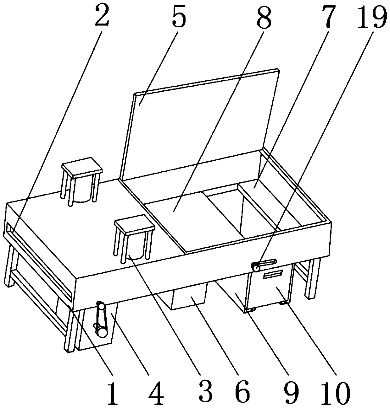
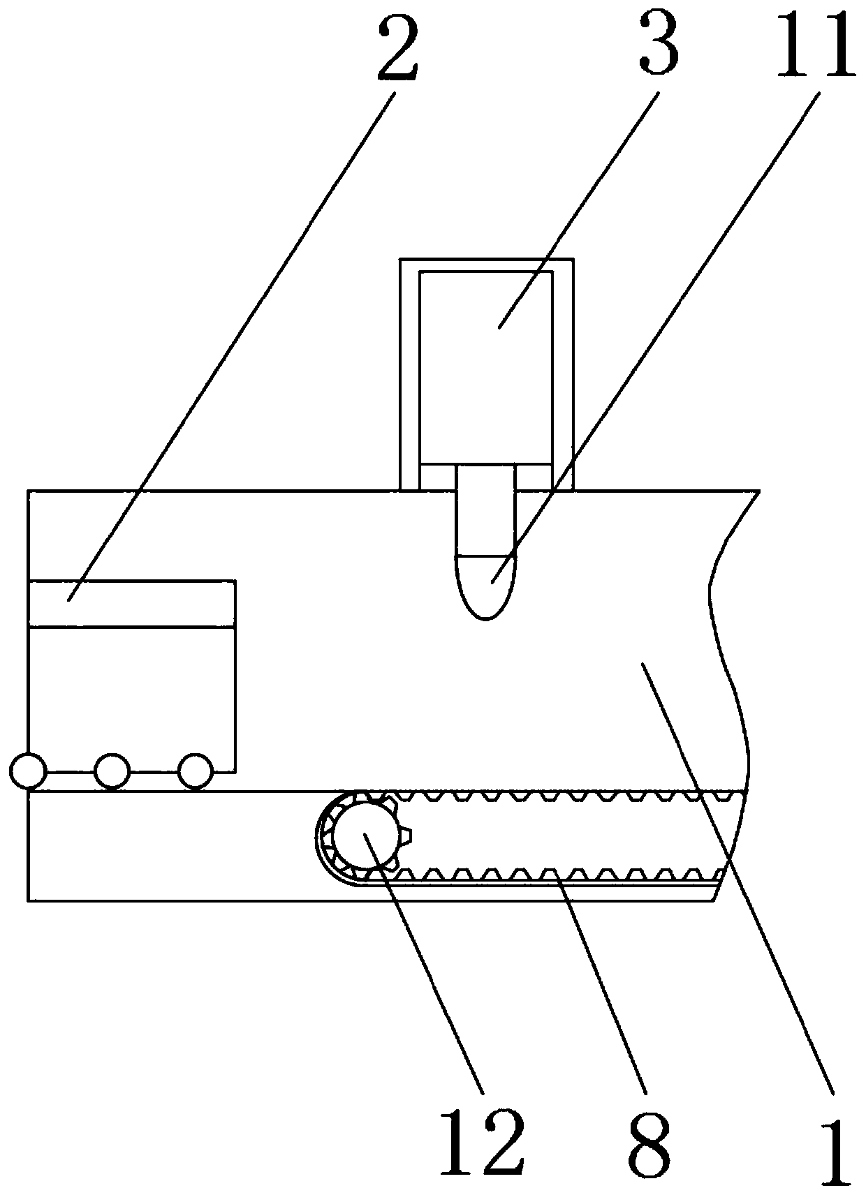
[0031] refer to Figure 1-2 , a broken tempered glass recovery device, comprising a recovery device shell 1, the internal front end of the recovery device shell 1 is fixed with a feed frame 2 by bolts, and the outer surface of the top end of the recovery device shell 1 is fixed by bolts on both sides of the front end A hydraulic rod 3 is installed, and the outer surface of the bottom end of the hydraulic rod 3 is welded with a striking head 11, the outer surface of the bottom end of the recovery device shell 1 is welded with a motor box 4 near the front end, and the top outer surface of the recovery device shell 1 is close to the rear end The position is installed with a movable plate 5 through the hinge movement, and the outer surface of the bottom end of the recovery device shell 1 is welded with a reserved box 6 near the center. A guide frame 9 is welded near the rear end, and a guide chute 13 is welded on the inner surface of the inner wall 7 .
[0032] refer to figure 1...
Embodiment 2
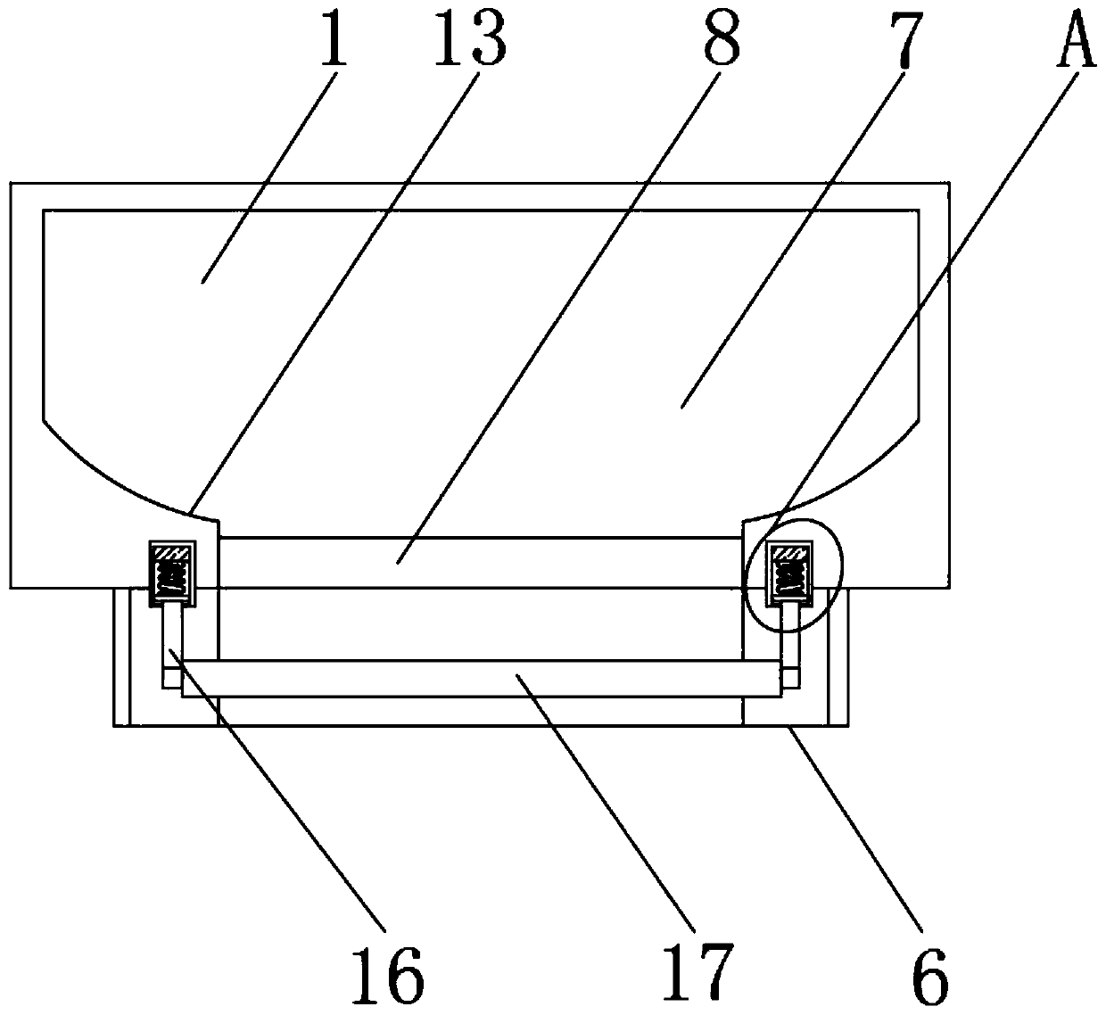
[0039] refer to Figure 2-6A fixed frame 14 is welded between the recovery device shell 1 and the reserved box 6 near both sides, and the inner surface of the fixed frame 14 is fixed with a pressure sensor 15 by bolts near the outer surface of the top end, and the outer surface of the bottom end of the pressure sensor 15 is A connecting rod 16 is movably installed by a spring, a conveyor belt 8 is movably installed on the inner surface of the inner wall 7 near the center, and a drive roller 12 is fixedly installed inside the conveyor belt 8 near the front end, and a pressure roller is welded on the outer surface of the bottom end of the connecting rod 16 17, and the top of the pressure roller 17 is fixedly installed near both sides of the pinch roller 18, and the inside of the conveyor belt 8 is movably installed with a movable roller 19 near the rear end.
[0040] refer to Figure 4 , The inner surface of the fixed frame 14 is provided with a guide groove, which facilitates ...
Embodiment 3
[0044] refer to figure 1 , Figure 6 and Figure 7 The inside of the guide frame 9 is movably equipped with a collection box 10, and the front end of the collection box 10 is movably equipped with a dodge door 20 through a hinge, and two electric telescopic rods 21 are fixedly installed in the inside of the collection box 10.
[0045] refer to Figure 7 , the inside of the collection box 10 is provided with a retractable groove, and two storage boxes are installed for the movement of the retractable groove. The handle is capable of pulling the collection box 10 outward.
[0046] refer to Figure 7 , the outer surface of the bottom of the collection box 10 near the four corners is fixed with pillars by bolts, the outer surface of the bottom of the pillars is movably equipped with rollers through the rotating shaft, rollers are installed at the bottom of the collection box 10, and the collection box is convenient 10 slides.
[0047] There are two storage boxes installed in...
PUM
Abstract
The invention discloses a toughened-glass crushing and recycling device. The toughened-glass crushing and recycling device comprises a recycling device shell, the front end of the interior of the recycling device shell is fixedly provided with a feeding frame through bolts, hydraulic rods are fixedly installed on the outer surface of the top end of the recycling device shell and near the two sidesof the front end through bolts, striking heads are welded to the outer surfaces of the bottoms of the hydraulic rods, and a motor box is welded to the position, close to the front end, of the outer surface of the bottom of the recycling device shell. According to the toughened-glass crushing and recycling device, the spatter range of crushed glass can be limited, the interior of the device can beconveniently observed and repaired, elongation and shortening of a conveyor belt can be changed, glass fragments can be controlled to enter different storage tanks so that the glass fragments of different materials can be conveniently classified and stored, pressure change can be detected through a pressure sensor, and a storage box can be pushed out and replaced through an electric telescopic rod, so that a better application prospect is brought.
Description
technical field [0001] The invention relates to the field of recycling devices, in particular to a broken and recycled tempered glass device. Background technique [0002] In the industry, tempered glass is processed into float glass in the form of glass slag as a reference material. Tests have shown that glass containers made of recycled glass have the same wall transparency and container strength as glass containers made of new raw materials. The same, and the use of recycled secondary materials can save 38% of energy, reduce 50% of air pollution, 20% of water pollution and 90% of waste compared with raw materials to make glass products, so tempered glass broken recycling equipment is needed; [0003] The existing tempered glass crushing and recovery device has certain disadvantages in use, and the safety is insufficient. In the patent number: CN207576500U, there is no protective measure when the glass is broken, which makes the glass fragments splash everywhere when broke...
Claims
Application Information
Patent Timeline
Application Date:The date an application was filed.
Publication Date:The date a patent or application was officially published.
First Publication Date:The earliest publication date of a patent with the same application number.
Issue Date:Publication date of the patent grant document.
PCT Entry Date:The Entry date of PCT National Phase.
Estimated Expiry Date:The statutory expiry date of a patent right according to the Patent Law, and it is the longest term of protection that the patent right can achieve without the termination of the patent right due to other reasons(Term extension factor has been taken into account ).
Invalid Date:Actual expiry date is based on effective date or publication date of legal transaction data of invalid patent.

