
Blast furnace roof flange installing method

A flange installation, blast furnace technology, applied in auxiliary devices, auxiliary welding equipment, welding/cutting auxiliary equipment, etc., can solve problems such as hidden dangers in safety production, blast furnace gas leakage in the furnace top area, and intermediate process monitoring, and achieve improved accuracy. and quality, reduce construction costs, and improve the effect of installation quality

Inactive Publication Date: 2019-05-17
SHANGHAI ERSHIYE CONSTR CO LTD +1
View PDF4 Cites 4 Cited by
  • Summary
  • Abstract
  • Description
  • Claims
  • Application Information

AI Technical Summary

Problems solved by technology

[0008] The above requirements are due to: if the above requirements are not met, the seal between the bell and the bell seat will be affected when the bell valve type furnace roof is used; when the bellless furnace roof is used, the rotating distributor will be driven The base of the gear box is deformed, which will lead to premature failure of the gear box; at the same time, it will also affect the seal between the furnace roof equipment and the furnace roof flange. Blast furnace gas leakage occurred in the roof area, causing serious safety hazards
[0009] The main feature of the traditional process is that only the jump-back welding method is used, and the intermediate process is not monitored. The requirements for the installation of material equipment need to be processed later

Method used


Image

  • Blast furnace roof flange installing method

Examples


Embodiment Construction

[0032] Below in conjunction with specific embodiment, further illustrate the present invention. It should be understood that these examples are only used to illustrate the present invention and are not intended to limit the scope of the present invention. In addition, it should be understood that after reading the teachings of the present invention, those skilled in the art can make various changes or modifications to the present invention, and these equivalent forms also fall within the scope defined by the appended claims of the present application.

[0033] In Shangang 2#5100m 3 In the blast furnace project, an improved blast furnace roof flange installation method is adopted, including the following steps:

[0034] (1) Preheat flange 1 to 200°C by electric heating before welding.

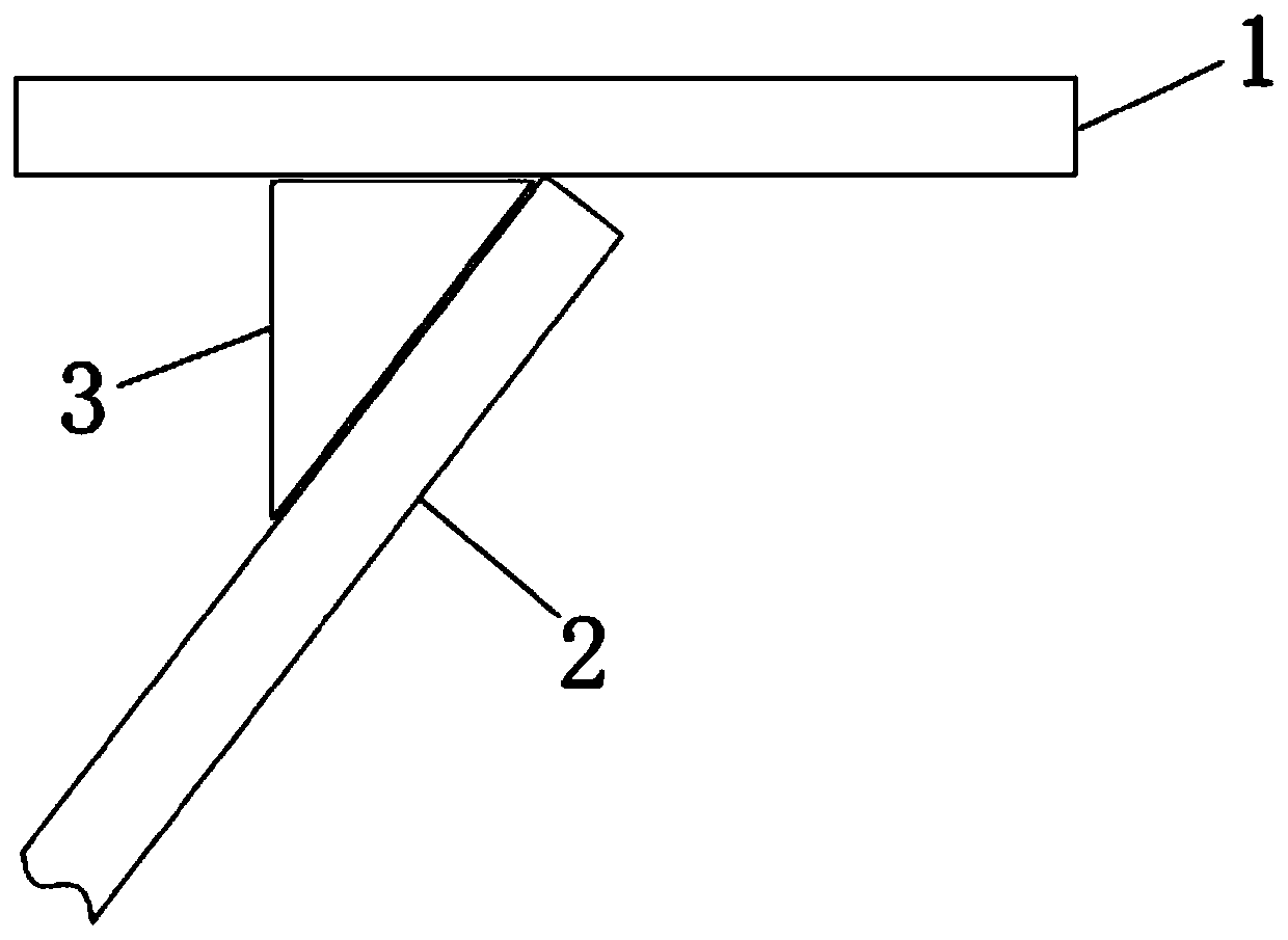
[0035] (2) Rigid fixing method is used to strengthen and constrain flange 1 with ribs 3 : ribs 3 are evenly spaced around the outer periphery of the furnace roof along the circumferential dire...


PUM


Abstract

The invention relates to a blast furnace roof flange installing method. Preheating is conducted to 190-210 DEG C before welding; rib plates are adopted for strengthening a flange for restraining deformation, and the rib plates are arranged along the periphery of a furnace roof at equal intervals; preliminary leveling is conducted on the flange, and after leveling, welding lines between the rib plates and a furnace body are leveled; accurate leveling is conducted on the flange, four-point leveling is conducted on the flange along the flange center according to cross symmetry, vertical welding lines between the corresponding rib plates in the four-point direction and the flange are subjected to spot welding, and after accurate flange leveling and spot welding of the vertical welding lines between all the rib plates and the flange are gradually finished according to the above manner, the vertical welding lines between all the rib plates and the flange are welded through a skip reverse welding method; and during flange welding, welding is synchronously conducted along the flange center according to the four-point positions of the cross center line, a segmented reverse welding method isadopted in welding, and synchronous reversing is conducted in the welding process. In the flange welding process, a balance level and an invar ruler are adopted for welding deformation monitoring. Bymeans of the blast furnace roof flange installing method, the flange installing quality can be improved, the construction period is shortened, and the construction cost can be better reduced.

Description

technical field [0001] The invention belongs to the technical field of flange installation, and in particular relates to a method for installing a blast furnace roof flange. Background technique [0002] Blast furnace top charging equipment, whether it adopts bell-valve type top charging equipment or bellless top charging equipment, if the equipment directly connected to the top flange or the gap between the equipment and the top flange When there is a problem with the seal and needs to be overhauled, it is quite troublesome to deal with. If the installation quality of the furnace top flange is not good or the seal is not handled properly, it will directly affect the service life of the furnace top charging equipment, thereby affecting the generation life of the blast furnace and affecting the production efficiency of the owner. [0003] The relevant national construction specifications and technical documents of manufacturers of modern blast furnace roof equipment usually ...

Claims


Application Information

Patent Timeline
IPC IPC(8): B23K31/02B23K37/00
Inventor 左建伍宇
Owner SHANGHAI ERSHIYE CONSTR CO LTD
Learn More