Drilling and polishing integrated multiple-hole-diameter conversion drilling machine capable of detecting machining situation
A multi-aperture, drilling and grinding technology, applied in the field of drilling machines, can solve problems such as time-consuming and laborious, inability to detect processing conditions, and inability to accurately sense processing problems.
- Summary
- Abstract
- Description
- Claims
- Application Information
AI Technical Summary
Problems solved by technology
Method used
Image
Examples
Embodiment 1
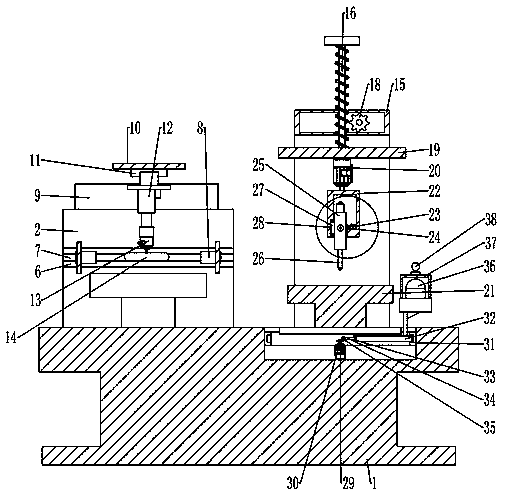
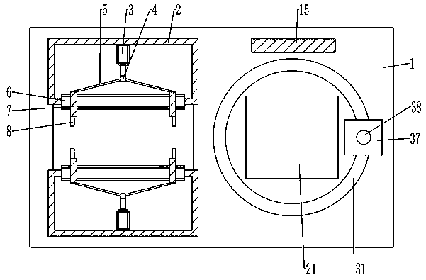
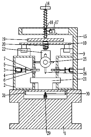
[0058] Embodiment 1: According to Figure 1-4 , when using this frame 1, the plate-shaped workpiece to be processed is placed between the fixed frames 2 on the upper surface of the frame 1, and then the power is turned on. At this time, the driving end of the cylinder 3 installed on the inner wall of the fixed frame 1 is extended. , which drives the hinge 4 mounted on it to move forward. Since the push rod 5 is movably connected to both sides of the fold 4, the end of the other side of the push rod 5 will move to both sides at this time, and the other end of the push rod 5 will move to both sides. The end on one side is connected to the side wall of the slider 7, so it will push the slider 7 to move to both sides in the chute 6, when the fastening plate 8 installed on the other side wall tightens the workpiece tightly After the clamping, the vertical electric slide rail 9 moving seat 9 installed on the upper surface of the fixed frame 2 moves to one side at the same time, driv...
Embodiment 2
[0059] Embodiment 2: For the displacement mechanism in the omnidirectional detection unit, in addition to the linear displacement, according to Figure 4 As mentioned above, when workpiece detection is required, the driving end of the driving motor 39 installed in the frame 1 rotates, which drives the rotation of the gear 40 installed thereon. Since the rack plate 41 meshes with it, the rack plate 41 will do reciprocating linear motion through the slide block at its bottom. Since the lifting rod 43 is movably connected to the end on one side, when the rack plate 41 moves to the right, it will pull the lower end of the lifting rod 43. When the head moves to the right, due to the restriction of the rotating seat 42, the upper end of the lifting rod 43 will move to the left, so that the height of the camera 36 installed on its end becomes higher, so that the camera 36 slowly stretches out , and then the workpiece is remotely monitored. When monitoring is not required, the rack pl...
Embodiment 3
[0060] Embodiment 3: For workpieces of different shapes and specifications, according to Figure 5 As shown, the circular workpiece is placed between the grinding grooves 47, and then the double-seat slide rails 45 installed on the upper surface of the grinding seat 44 will move toward each other, so that the adapting motor 46 mounted thereon will move toward each other. When the grinding grooves After 47 adapted to the size of the circular workpiece, the two-seat slide rail 45 moving seats stopped moving, and the adapting motor 46 driving end that was installed on it now rotated, driving the grinding groove 47 that was installed on it to rotate, constantly to The surface of the circular workpiece is polished, and the damping spring 48 installed in the grinding seat 44 is used to increase the damping effect and prevent from affecting its grinding quality.
PUM
 Abstract
Description
Claims
Application Information
 - R&D
- Intellectual Property
- Life Sciences
- Materials
- Tech Scout
- Unparalleled Data Quality
- Higher Quality Content
- 60% Fewer Hallucinations
Browse by: Latest US Patents, China's latest patents, Technical Efficacy Thesaurus, Application Domain, Technology Topic, Popular Technical Reports.
© 2025 PatSnap. All rights reserved.Legal|Privacy policy|Modern Slavery Act Transparency Statement|Sitemap|About US| Contact US: help@patsnap.com


