Open type single crankshaft steel frame machine tool

A steel frame and machine tool technology, applied in the field of open single-crank steel frame machine tools, can solve the problems of easy steel plate springback, inconvenient assembly and disassembly, heavy machine tool weight, etc., to achieve the elimination of residual austenite, simple and clear structure , The effect of reducing the weight of the machine tool

Active Publication Date: 2019-05-17
安徽远都机床股份有限公司
View PDF10 Cites 0 Cited by
  • Summary
  • Abstract
  • Description
  • Claims
  • Application Information

AI Technical Summary

Problems solved by technology

[0003] The object of the present invention is to provide an open type single crank steel frame machine tool. The machine tool itself does not provide power to reduce the weight of the machine tool. The structure is simple and clear, and it is easy to assemble and disassemble. The weight-increasing area satisfies the stability, reduces the weight of the machine tool, reduces the cost, adjusts the distance between the left mobile end and the right mobile end closer, makes the left mobile end and the right mobile end integrated and only realizes the function of transporting steel plates, and adjusts the left The distance between the moving end and the right moving end, the steel plate can eliminate the residual austenite inside the steel plate after stamping to a certain extent through the bending and turning between the left moving end and the right moving

Method used


Image

  • Open type single crankshaft steel frame machine tool
  • Open type single crankshaft steel frame machine tool
  • Open type single crankshaft steel frame machine tool

Examples


Embodiment Construction

[0024] The following will clearly and completely describe the technical solutions in the embodiments of the present invention with reference to the accompanying drawings in the embodiments of the present invention. Obviously, the described embodiments are only some, not all, embodiments of the present invention. Based on the embodiments of the present invention, all other embodiments obtained by persons of ordinary skill in the art without making creative efforts belong to the protection scope of the present invention.

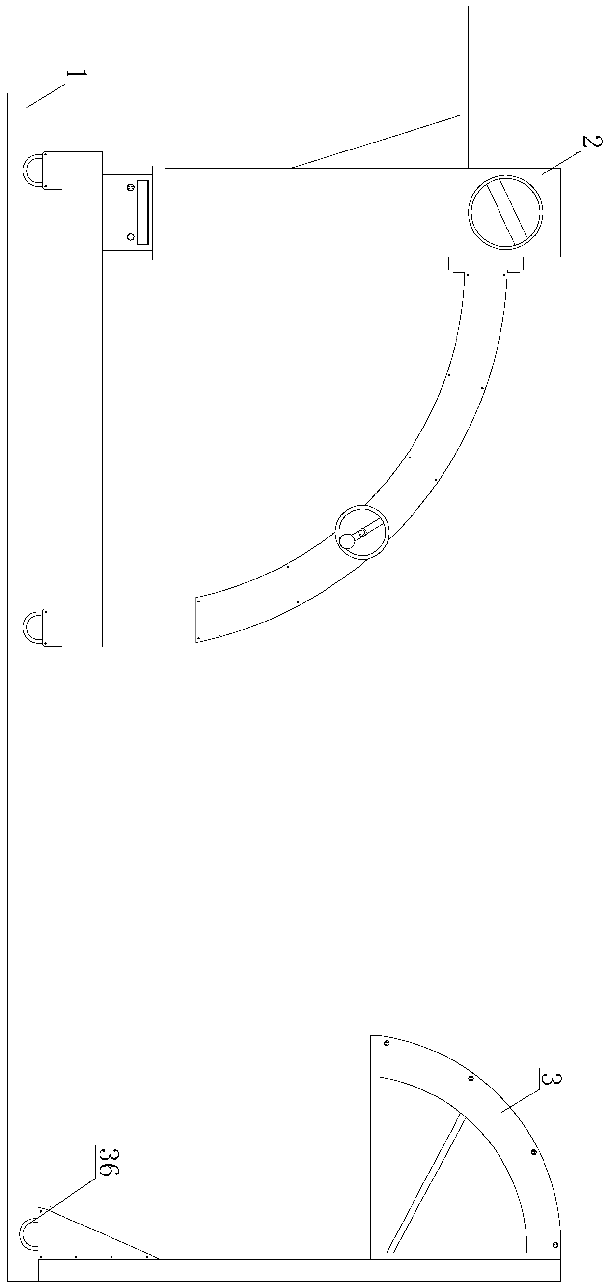
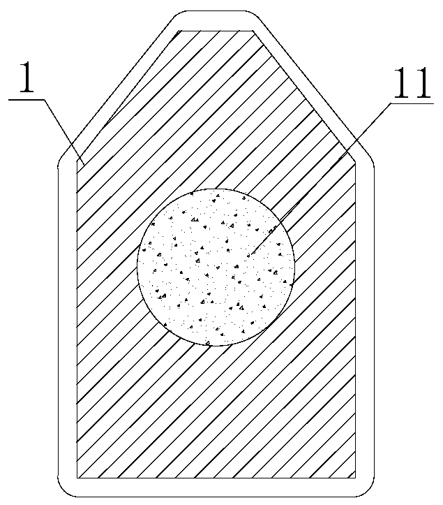
[0025] see Figure 1-2 , an open single-crank steel frame machine tool, including a base 1, a left moving end 2 and a right moving end 3, the base 1 is two groups of block structures arranged side by side, and the cross-sectional shape of the two groups of bases 1 is set to be positive at the top The trapezoidal solid structure, the inside of the base 1 is provided with a weight-increasing area 11, the top of the base 1 is chamfered, and the top of the base 1 ...


PUM


Abstract

The invention discloses an open type single crankshaft steel frame machine tool. The open type single crankshaft steel frame machine tool comprises a base, a left moving end and a right moving end, wherein a stamped steel plate is rolled by a first rotating shaft and a second rotating shaft to be conveyed into a steel plate leveling device, power in the steel plate moving process is provided by aconnecting device, and the machine tool does not provide power; the weight of the machine tool is reduced, the structure is simple and clear, and the assembling and disassembling are convenient, the height of the left moving end is adjusted by an air cylinder and an ejector rod; and the practicability is increased, the setting of a weighting area meets the stability and reduces the weight of the machine tool, the cost is reduced, the distance between the left moving end and the right moving end is adjusted to be close to enable the left moving end and the right moving end to be integrated andthe function of transporting the steel plate is only realized, the distance between the left moving end and the right moving end is adjusted to be far away, and the steel plate eliminates the residualaustenite in the punched steel plate to a certain extent through bending rotation between the left moving end and the right moving end, the proportion of martensite is increased, the residual stressis eliminated, the quality of the steel plate is improved, and the practicability is increased.

Description

technical field [0001] The invention relates to the technical field of mechanical processing, in particular to an open single-crank steel frame machine tool. Background technique [0002] The steel plate is a flat-shaped steel material that is poured with molten steel and pressed after cooling. During the production process of the steel plate, the press machine stamps the steel plate and sends it directly to the leveling device through the conveying device. During the conveying process, the steel plate is prone to rebound. The residual austenite inside the steel plate cannot be eliminated in a timely and effective manner, resulting in low plasticity and poor quality of the steel plate, which cannot meet the high requirements of modern science and technology and industrial development for material properties. A few manufacturers add auxiliary machine tools after the press. To provide power for the transportation of steel plates, the machine tool is heavy and has a complicated...

Claims


Application Information

Patent Timeline
IPC IPC(8): B30B1/26B30B15/04
Inventor 林鹏丘添元
Owner 安徽远都机床股份有限公司
Why Eureka
Try Eureka