Hydraulic decoupling type electro-hydraulic braking system

A hydraulic braking and hydraulic technology, applied in the direction of brakes, brake transmission devices, foot-operated starting devices, etc., can solve the problems of inability to freely match ESC modules, complex mechanical structures, etc., achieve simple structure and low cost, and meet the requirements of pressure building and Effect of Response to Demand, High Energy Recovery Efficiency

Inactive Publication Date: 2019-05-17
上海擎度汽车科技有限公司
View PDF4 Cites 21 Cited by
  • Summary
  • Abstract
  • Description
  • Claims
  • Application Information

AI Technical Summary

Problems solved by technology

However, the mechanical structures of these two products are too complicated to freely match ESC modules, and the cost is about 2 to 3 times that of traditional vacuum boosters.

Method used


Image

  • Hydraulic decoupling type electro-hydraulic braking system

Examples


Embodiment Construction

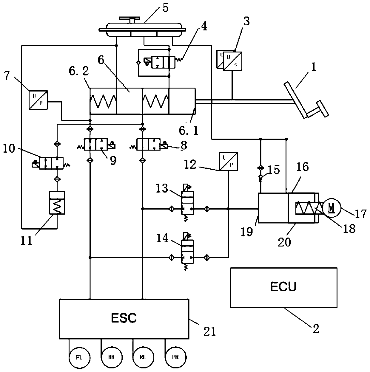
[0063] Such as figure 1 As shown, the hydraulic decoupling electronic hydraulic braking system provided by the present invention includes: pedal assembly 1, ECU2, pedal displacement sensor 3, self-check valve 4, liquid storage tank 5, master cylinder 6, first hydraulic pressure sensor 7. The first isolation valve 8, the second isolation valve 9, the simulator control valve 10, the pedal feeling simulator 11, the second hydraulic pressure sensor 12, the first suction valve 13, the second suction valve 14, the one-way valve 15 and Active pressure building unit 16;

[0064] The pedal displacement sensor 3 collects 1 stroke of the pedal assembly. The master cylinder 6 has the first chamber 6.1 of the master cylinder and the second chamber 6.2 of the master cylinder. The first chamber 6.1 of the master cylinder and the second chamber 6.2 of the master cylinder are airtightly connected. The first cavity 6.1 and the second cavity 6.2 of the master cylinder are respectively equipped ...


PUM


Abstract

The invention discloses a hydraulic decoupling type electro-hydraulic braking system which comprises a pedal displacement sensor for collecting a stroke of a pedal assembly, wherein a first isolationvalve and a second isolation valve are respectively arranged on outlets of a first cavity and a second cavity of a master cylinder; the outlet of the first cavity of the master cylinder is connected with an inlet of a simulator control valve in parallel; a liquid storage tank is connected with the first cavity and the second cavity of the master cylinder, an active pressure buildup unit and a pedal feel simulator of the master cylinder are connected by a pipeline; a one-way valve is arranged on a parallel pipeline; a first hydraulic pressure sensor is arranged in the second cavity of the master cylinder; a second hydraulic pressure sensor is arranged at the outlet of the active pressure buildup unit; a self-check valve is arranged between the first cavity of the master cylinder and the outlet of the liquid storage tank; a first suction valve and a second suction valve are arranged at the outlet of the active pressure buildup unit in parallel; the pipeline where the first suction valveis located is connected between the first isolation valve and the ESC module; the pipeline where the second suction valve is located is connected between the second isolation valve and the ESC module;and an ECU controls the self-check valve, the first isolation valve, the second isolation valve, the first suction valve, the second suction valve, the simulator control valve and the active pressurebuildup unit.

Description

technical field [0001] The invention relates to the field of automobiles, in particular to an automobile hydraulic decoupling electronic hydraulic braking system. Background technique [0002] With the promotion of new energy vehicles and the continuous advancement of vehicle chassis technology, the requirements for vehicle energy recovery and advanced driver assistance functions continue to increase. Due to the limitation of the non-decoupled mechanical structure, the traditional vacuum booster braking system has disadvantages such as large volume, unable to directly support energy recovery, unable to realize active braking, and unable to freely adjust the boost ratio. [0003] Therefore, in the past ten years, the electro-hydraulic braking system that overcomes the above-mentioned shortcomings of the vacuum booster has been gradually pushed to the market. Among them, Bosch IPB, Continental MK C1 and other integrated electro-hydraulic brake systems are representative. The...

Claims


Application Information

Patent Timeline
Patent Type & Authority Applications(China)
IPC IPC(8): B60T13/68B60T13/14B60T8/40B60T7/06
Inventor 张弘弢董明哲见才涛孟凡雪徐松云
Owner 上海擎度汽车科技有限公司
Why Eureka
Try Eureka