Eureka AIR delivers breakthrough ideas for toughest innovation challenges, trusted by R&D personnel around the world.

Brick blank clamping and conveying clamp device with rotation function

A technology of rotating function and clamping device, which is applied in the direction of transportation and packaging, object stacking, conveyor objects, etc., can solve the problems of increasing labor intensity of workers, affecting the quality of brick production, affecting production efficiency, etc., and achieves simple structure and design Novel and easy-to-operate effects

Pending Publication Date: 2019-05-17
SHAANXI BAOSHEN MACHINERY GROUP
View PDF0 Cites 4 Cited by
  • Summary
  • Abstract
  • Description
  • Claims
  • Application Information

AI Technical Summary

Problems solved by technology

[0002] With the development of society and the acceleration of the mechanized operation process, the operation form of manual handling of bricks is gradually replaced by mechanization. After clamping and transporting to the destination, the plywood resets and leaves the adobe. Since this kind of adobe clamping fixture has no rotation function, the stacking of adobes after the next adobe clamping can only be stacked upwards according to the length and width of the adobes. This stacking method, stacking There is no gap between the stacked bricks, which affects the production of the subsequent process steps. On the other hand, the outer bricks are easy to fall, which affects the production quality of the bricks. To eliminate the disadvantages caused by the above stacking method, when the bricks are stacked, It is necessary to manually rotate the bricks and stack them upwards, thereby eliminating the above-mentioned disadvantages of directly stacking upwards, which seriously affects the production efficiency and increases the labor intensity of the workers. In view of the above problems, it is necessary to improve

Method used


Image

  • Brick blank clamping and conveying clamp device with rotation function
  • Brick blank clamping and conveying clamp device with rotation function
  • Brick blank clamping and conveying clamp device with rotation function

Examples


Embodiment Construction

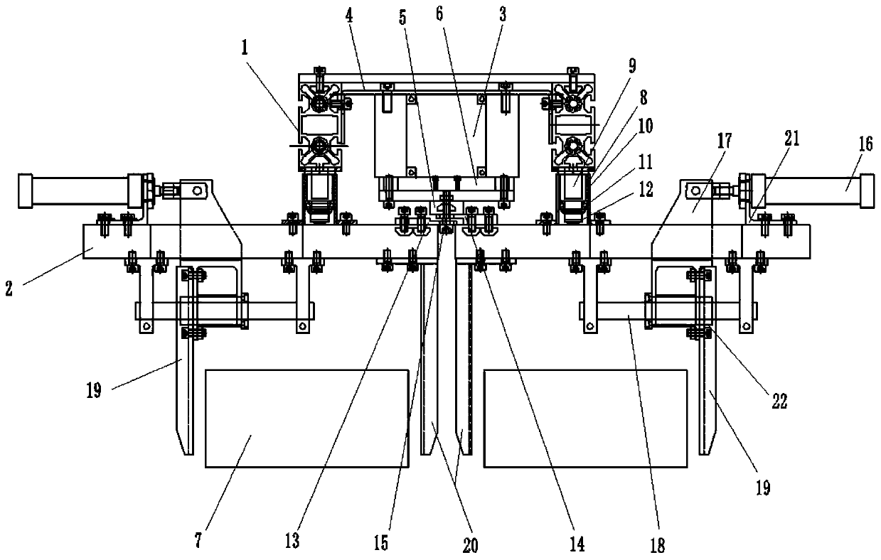
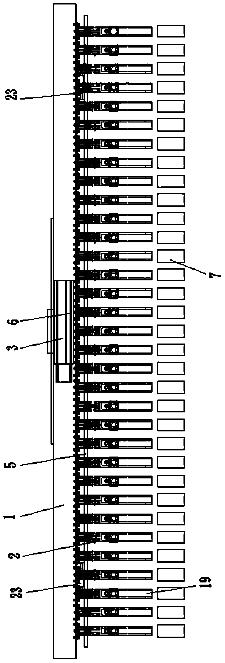
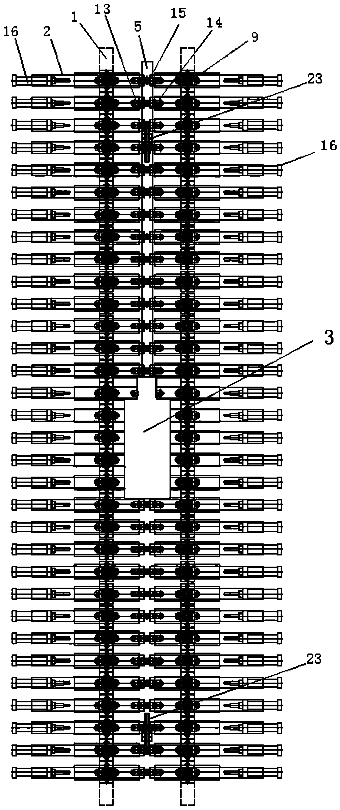
[0020] Attached below Figure 1-6 An embodiment of the present invention is described so as to clearly and completely describe the technical solution. Obviously, the described embodiment is only a part of the embodiments of the present invention, rather than all the embodiments.

[0021] In describing the present invention, it should be understood that the terms "upper", "lower", "front", "rear", "left", "right", "top", "bottom", "inner", " The orientation or positional relationship indicated by "outside", etc. is based on the orientation or positional relationship shown in the drawings, which is only for the convenience of describing the present invention and simplifying the description, rather than indicating or implying that the referred device or element must have a specific orientation, so as to Specific orientation configurations and operations, therefore, are not to be construed as limitations of the invention.

[0022] The jig device for brick clamping with rotation f...


PUM


Abstract

The invention provides a brick blank clamping and conveying clamp device with a rotation function. A plurality of blank clamping rods below connecting beams are perpendicular to the connecting beams and are connected with the connecting beams through rotation supporting devices. A linear module is arranged between the two connecting beams and fixedly connected with the connecting beams through bent connecting plates. A connecting rod below the linear module is fixedly connected with a linear module sliding block in the linear module. The inner sides of the two blank clamping rods located on the same straight line are connected with the connecting rod through synchronous pieces. After the linear module drives the connecting rod to move in the length direction of the linear module, the blankclamping rods and brick blanks clamped through clamping devices are driven to synchronously rotate. The rotation supporting devices are adopted for connecting the blank clamping rods and the connecting beams, and after the linear module is used for driving the connecting rod connected with the blank clamping rods to move, synchronous rotation of the blank clamping rods and the brick blanks is achieved; and mechanical operation of brick blank stacking is achieved while the subsequent technology steps are not influenced, manual upward overlaying and stacking are not needed, the labor intensityof manual work is lowered, and the brick blank production quality and efficiency are improved.

Description

technical field [0001] The invention belongs to the technical field of adobe clamping and transporting, and in particular relates to a jig device for adobe clamping with a rotating function. Background technique [0002] With the development of society and the acceleration of the mechanized operation process, the operation form of manual handling of bricks is gradually replaced by mechanization. After clamping and transporting to the destination, the plywood resets and leaves the adobe. Since this kind of adobe clamping fixture has no rotation function, the stacking of adobes after the next adobe clamping can only be stacked upwards according to the length and width of the adobes. This stacking method, stacking There is no gap between the stacked bricks, which affects the production of the subsequent process steps. On the other hand, the outer bricks are easy to fall, which affects the production quality of the bricks. To eliminate the disadvantages caused by the above stack...

Claims


Application Information

Patent Timeline
Patent Type & Authority Applications(China)
IPC IPC(8): B65G47/90B65G57/081B65G57/03
Inventor 林永淳张军仓王阿娟师晓明
Owner SHAANXI BAOSHEN MACHINERY GROUP
Why Eureka
Eureka Blog
Learn More