
A small rapid heating and cooling annealing device suitable for quantum chips

An annealing device and heating and cooling technology, applied in the direction of furnace type, furnace, heat treatment equipment, etc., can solve the problems of slow heat dissipation of the system, complicated use of equipment, and inability to control the cooling speed, etc., and achieve the effect of precise control of the heating and cooling speed

Active Publication Date: 2020-08-28
广州量子湾科技有限公司
View PDF3 Cites 0 Cited by
  • Summary
  • Abstract
  • Description
  • Claims
  • Application Information

AI Technical Summary

Problems solved by technology

[0003] In the prior art, it is very difficult to use the same device to achieve both rapid temperature rise and rapid cooling. Generally, it is difficult to quickly cool down a system that is easy to achieve rapid temperature rise, and it is difficult to heat up a system that is easy to cool down.
Usually, the temperature of the system can be raised and lowered in the following ways: first, use semiconductor heat sinks to achieve temperature rise and fall, but semiconductor heat sinks can only be used in the range near normal temperature, and this method is not feasible for high-temperature application scenarios; second, use Open the furnace body to realize large-area rapid heat dissipation, but this method needs to open the furnace body during the high temperature process. Although it can achieve rapid cooling, the cooling rate cannot be controlled, and the process of opening the furnace body is also very dangerous for users; Third, use Water cooling realizes rapid cooling, but this method is not conducive to rapid temperature rise of the system due to the complexity of the device used and the relatively large specific heat of water, so it is not easy to achieve rapid temperature rise and fall of the system at the same time; Fourth, the use of high-power heating elements enables the system to Rapid heating, this method consumes a lot of energy, but the system may have a certain heat preservation function due to the high-power heating element placed around the workpiece to be processed, which slows down the heat dissipation of the system and also affects the rapid cooling speed of the workpiece to be processed

Method used


Image

  • A small rapid heating and cooling annealing device suitable for quantum chips
  • A small rapid heating and cooling annealing device suitable for quantum chips
  • A small rapid heating and cooling annealing device suitable for quantum chips

Examples


Embodiment Construction

[0024] The technical solution of the present invention will be further described in detail below in conjunction with the accompanying drawings, but the protection scope of the present invention is not limited to the following description.

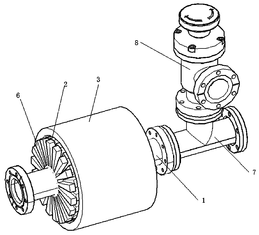
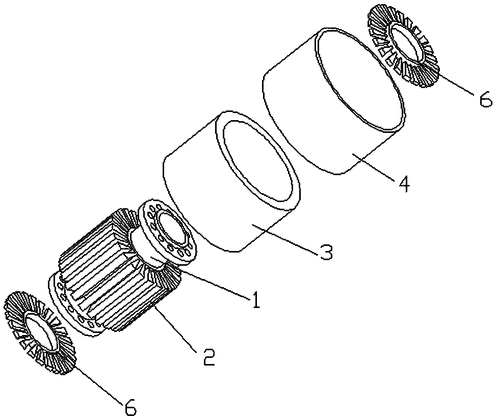
[0025] Such as figure 1 As shown, a rapid heating and cooling annealing device suitable for quantum chips includes a vacuum chamber 1, a gas flow control valve a is provided at one end of the vacuum chamber 1, and a tee 7 is connected at the other end. The top of the tee 7 is connected with a sealing angle valve 8, and the other end of the tee 7 is connected with an electric lead wire electrode. The electrical series lead electrode includes a flange and a transmission wire. The flange is used to seal the end of the tee 7 , and the transmission wire can transmit electrical signals from the airtight vacuum chamber 1 to the outside of the tee 7 . The other end of the sealing angle valve 8 is connected with a vacuum pump. When the flow contro...


PUM


Abstract

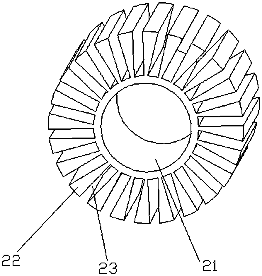
The invention discloses a small rapid temperature rise and reduction annealing device suitable for a quantum chip and an application thereof, and relates to the field of electrode material treatment devices. The small rapid temperature rise and reduction annealing device comprises a vacuum chamber; the vacuum chamber is sleeved with a radiating device and a heating sleeve sequentially; the radiating device comprises a mounting sleeve; a plurality of radiating fins are uniformly distributed at the exterior of the mounting sleeve; one ends, far away from the mounting sleeve, of the radiating fins are arranged in contact with the heating sleeve; and a radiating hole is formed between every two adjacent radiating fins. The small rapid temperature rise and reduction annealing device can use thesame device to realize the processes of rapid temperature rise and reduction. The small rapid temperature rise and reduction annealing device is simple in structure and small in size, can meet the use requirements of a high temperature and a low temperature, and is low in energy consumption.

Description

technical field [0001] The invention relates to the field of electrode material processing devices, in particular to a rapid temperature rise and fall annealing device suitable for quantum chips. Background technique [0002] In ion trap quantum computers, gold electrodes are needed to capture and control trapped ions in ultra-high vacuum. Trapped ion electrodes take advantage of the high conductivity of metals, usually using gold as the conductive layer. The treatment of the electrode surface will directly affect the roughness of the electrode surface, which will lead to uneven changes in the surface electric field distribution when the voltage is applied, thereby affecting the time and stability of trapped ions. Therefore, after the electrode surface is plated with gold, in order to improve the surface quality of the gold and reduce the surface roughness, it is necessary to further perform a rapid heating annealing treatment on the gold, and the heating and cooling rate i...

Claims


Application Information

Patent Timeline
Patent Type & Authority Patents(China)
IPC IPC(8): C22F1/14C21D9/00
Inventor 吴思宇
Owner 广州量子湾科技有限公司
Learn More