Refrigeration tail end structure and refrigeration system

A technology of refrigeration capacity and refrigeration units, which is applied in the direction of refrigerators, refrigeration components, refrigeration and liquefaction, etc., can solve the problems of the overall energy efficiency reduction of the refrigeration system, the application obstruction of the refrigeration system, and the reduction of the evaporation temperature, so as to reduce the dry consumption of goods, the initial The effect of low investment cost and increased evaporation temperature

Inactive Publication Date: 2021-01-15
浙江英诺绿能科技有限公司
View PDF6 Cites 0 Cited by
  • Summary
  • Abstract
  • Description
  • Claims
  • Application Information

AI Technical Summary

Problems solved by technology

However, the shortcomings of the top-row tube method are very obvious. One is that the heat transfer temperature difference is large. The heat transfer temperature difference of the top-row tube method is usually 3-5K larger than that of the air cooler method, which will lead to a significant decrease in the overall energy efficiency of the refrigeration system. The slow speed will also increase the phenomenon of dry consumption of goods; the second is that defrosting is difficult and the defrosting cycle is long, and the evaporation temperature will decrease after frosting, which will lead to a decrease in energy efficiency; the third is that the initial investment is high and the filling volume is large, because The air convection velocity is close to zero, and the heat exchange area needs to be greatly increased to meet the demand for heat exchange. Therefore, the number of top row pipes is usually large, and the equipment cost is often more than three times that of the air cooler method, and the perfusion volume is even six times that of the air cooler method. about times
[0005] To sum up, in the actual application of cold storage, there are constant debates in the industry about the two refrigeration terminal structures, and it is difficult to reach a consensus. There are also certain difficulties in how to choose a reasonable choice for users. After the two refrigeration terminal structures are selected and set, each There are the above-mentioned defects, which hinder the application of refrigeration systems

Method used


Image

  • Refrigeration tail end structure and refrigeration system
  • Refrigeration tail end structure and refrigeration system
  • Refrigeration tail end structure and refrigeration system

Examples


Embodiment Construction

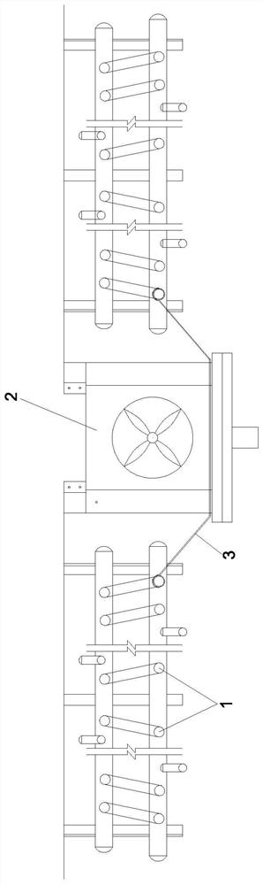
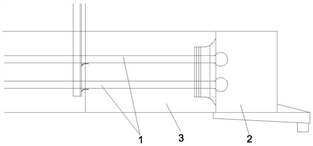
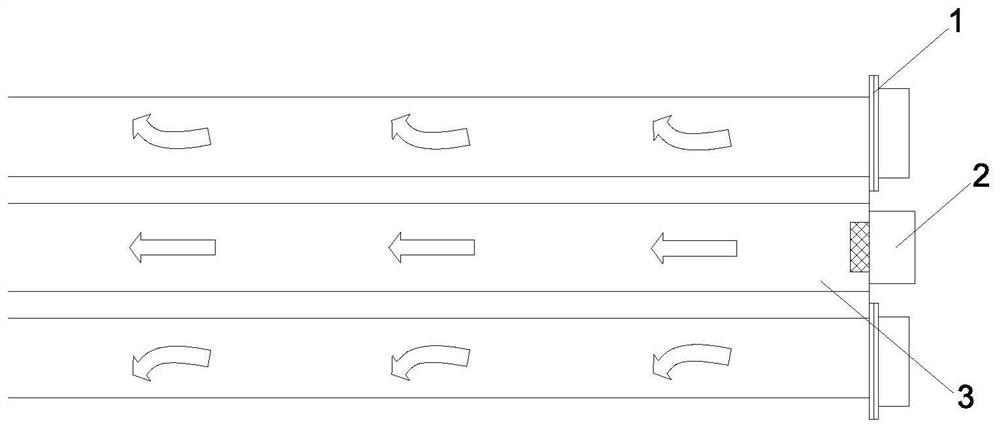
[0038] Such as Figure 1-Figure 3 As shown, a refrigeration terminal structure according to the present invention includes a top row pipe 1, a cooling fan 2, a liquid inlet pipe and a liquid return pipe; one end of the liquid inlet pipe is simultaneously connected to the liquid inlet end of the top row pipe 1 and the cooling fan 2 The liquid inlet end of the refrigerating unit 4 is connected to the other end. Specifically, the liquid inlet end of the top row pipe 1 is connected to the liquid inlet end of the cooling fan 2 and then connected to one end of the liquid inlet pipe. The other end of the pipe is connected to the liquid supply end of the refrigerating unit 4, and the refrigerating unit 4 inputs refrigerant to the top row pipe 1 and the cooling fan 2 through the liquid inlet pipe.

[0039] One end of the liquid return pipe is connected to the liquid outlet of the top row pipe 1 and the liquid outlet of the cooling fan 2 at the same time, and the other end is used to co...


PUM


Abstract

The invention discloses a refrigeration tail end structure and a refrigeration system, and relates to the technical field of refrigeration equipment. The refrigeration tail end structure comprises a top exhaust pipe, an air cooler, a liquid inlet pipe and a liquid return pipe, wherein one end of the liquid inlet pipe is simultaneously in communication with the liquid inlet end of the top exhaust pipe and the liquid inlet end of the air cooler while the other end is in communication with the liquid supply end of a refrigeration unit; one end of the liquid return pipe is simultaneously in communication with the liquid outlet end of the top exhaust pipe and the liquid outlet end of the air cooler while the other end is in communication with the liquid return end of the refrigeration unit; a first electromagnetic valve is arranged at the liquid inlet end of the top exhaust pipe, a pressure regulating valve is arranged at the liquid outlet end of the top exhaust pipe, and a second electromagnetic valve is arranged at the liquid inlet end of the air cooler; and the refrigeration system comprises the refrigeration unit and the refrigeration tail end structure. According to the refrigeration tail end structure and refrigeration system, the top exhaust pipe and the air cooler are arranged in a combined mode, the flow direction of a refrigerant is controlled through the electromagnetic valve, and the refrigeration tail end structure and the refrigeration system have the advantages of being high in refrigeration efficiency, low in energy consumption, low in initial investment cost, small in perfusion amount, low in drying consumption, high in cooling speed, stable and uniform in warehouse temperature, high in automation degree and small in occupied space.

Description

technical field [0001] The invention relates to the technical field of refrigeration equipment, in particular to a refrigeration terminal structure and a refrigeration system. Background technique [0002] At present, cold storage usually has two types of refrigeration terminal structures, each with its own advantages and disadvantages in actual use. [0003] The first is to use the cooling fan method, connecting the cooling fan to the refrigeration unit, the refrigeration unit inputs low-temperature refrigerant to the cooling fan, the cooling fan uses a specially designed heat exchanger coil, and matches the appropriate fan to output low-temperature cold air flow to make the temperature of the cold storage Lower to achieve cooling. The air cooler has the advantages of high heat exchange efficiency, fast cooling speed, large cooling capacity, fully automatic control, easy defrosting, small amount of refrigerant injection and controllable initial investment. However, if the...

Claims


Application Information

Patent Timeline
Patent Type & Authority Applications(China)
IPC IPC(8): F25D13/00F25D17/04F25D19/00F25D21/06F25D23/02F25D29/00F25B1/00F25B43/00F25B41/20F25B41/31
CPCF25B1/00F25B43/006F25D13/00F25D17/045F25D19/00F25D21/06F25D23/028F25D29/005
Inventor 顾众冉川东顾恩华
Owner 浙江英诺绿能科技有限公司
Why Eureka
Try Eureka