Corrugated steel-concrete composite beam

A technology of concrete and composite beams, applied in bridges, bridge materials, bridge construction, etc., can solve problems such as large deformation, stress concentration, stability of steel-concrete composite beams and damage to seismic performance, and achieve suppression of local buckling or overall failure. stability, good bearing capacity and ductility, and enhanced collapse resistance

Active Publication Date: 2019-05-17
JIANGNAN UNIV
View PDF6 Cites 4 Cited by
  • Summary
  • Abstract
  • Description
  • Claims
  • Application Information

AI Technical Summary

Problems solved by technology

[0005] Second, in strong earthquakes, the traditional steel-concrete beams are subjected to the earthquake, and the deformation is very large, and even some parts may be broken;
[0006] Third, for H-shaped steel-concrete beams, the flanges and webs bear different stress forms, and the whole length is welded together, which will affect each other's stress, resulting in stress concentration
[0007] The above problems have greatly reduced the integrity of the steel-concrete composite beam and caused damage to the stability and seismic performance of the steel-concrete composite beam.

Method used


Image

  • Corrugated steel-concrete composite beam
  • Corrugated steel-concrete composite beam
  • Corrugated steel-concrete composite beam

Examples


Embodiment 1

[0043] Example 1: A corrugated steel-concrete composite beam

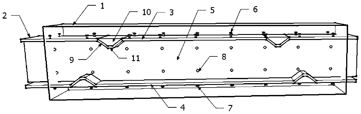
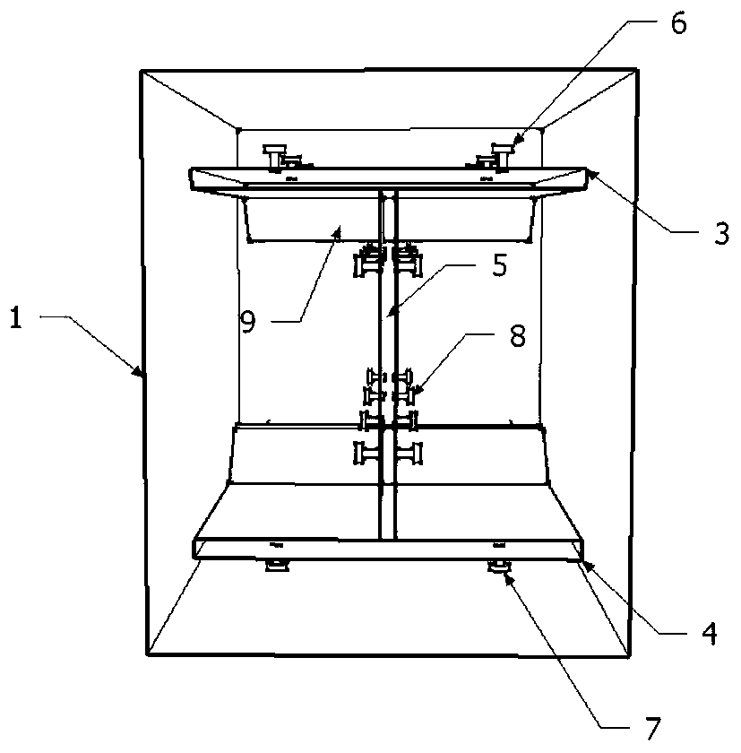
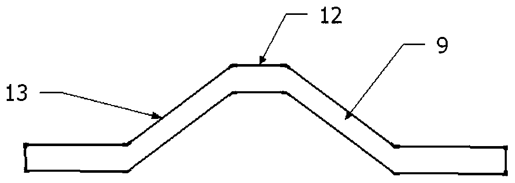
[0044] Such as Figure 1-3 , a corrugated steel-concrete composite beam includes concrete 1 and H-shaped steel 2 built into the concrete 1; The upper flange plate 3, the lower flange plate 4, the first bolt 6, the second bolt 7, and the third bolt 8 on the web 5; the upper flange plate 3 and the lower flange plate 4 are provided with "U ”-shaped wave 9; the wave direction of the “U”-shaped wave 9 faces the horizontal plane where the neutral axis of the beam is located; the inside of the “U”-shaped wave 9 is filled with lightweight filler material 10; the “U”-shaped The wave 9 is not connected to the web 5; the other side of the "U" wave 9 that is not in contact with the lightweight filling material 10 is separated from the concrete 1 by a non-stick film 11; the "U" wave 9 contains A bottom surface 12 and two side surfaces 13 .

[0045] As a further preference, the two sides (13) of the "U" wave 9 are of equal leng...

Embodiment 2

[0057] Example 2: Detection of a corrugated steel-concrete composite beam

[0058] Specific steps are as follows:

[0059] C40 ordinary concrete is used as the material of rectangular concrete, Q345 steel is used as the material of steel skeleton, the first bolt, the second bolt and the third bolt of M20*90 outer hexagonal hot-dip galvanized bolt type are selected, and phenolic foam material is selected; plastic As for the non-stick film, according to Example 1, a corrugated steel-concrete composite beam was prepared.

[0060] The span of the corrugated steel-concrete composite beam is 5m, and the section size is 250mm×450mm; the size of the upper flange plate is 200mm×6mm, the size of the lower flange plate is 200mm×8mm, and the height of the web is 320mm; There are two "U"-shaped waves on the flange plate and the lower flange plate; the distance between the wave centers of the two "U"-shaped waves on the upper flange plate and the beam end closer to it is five One-half bea...

Embodiment 3

[0062] Example 3: Detection of a corrugated steel-concrete composite beam

[0063] Specific steps are as follows:

[0064] Example 3 is based on Example 2, removing the non-stick film to prepare a corrugated steel-concrete composite beam.

[0065] According to the above-mentioned bending capacity testing method and ultimate deflection testing method, its ultimate bending capacity and ultimate deflection are measured, and the test results are: the ultimate bending capacity can reach 195kN·m, and the ultimate deflection can reach 50mm.


PUM


Abstract

The invention discloses a corrugated steel-concrete composite beam and belongs to the technical field of building and structural engineering. According to the corrugated steel-concrete composite beam,a corrugated beam section generates an obvious plastic hinge under the action of a major earthquake; a midspan section generates a crack first, and then the corrugated part is straightened. Therefore, the bending bearing capacity of the section of the corrugated part is enhanced, and then the yielding section of the beam is transferred to the midspan; the bearing force of the beam can also continue to be increased; when the midspan section is yielded, the deformation of the beam continues to be increased, and the bearing force is not increased any more till the beam is destroyed; through theadoption of the design, the corrugated steel-concrete composite beam is destroyed in prior to a column under the action of the earthquake so that the strong column and the weak beam are really realized; when the span of the corrugated steel-concrete composite beam is 5 m and the section dimension of the corrugated steel-concrete composite beam is 250mm*450mm, the ultimate bending bearing capacityof the corrugated steel-concrete composite beam can reach 212 kN.m, and the deflection limit of the corrugated steel-concrete composite beam can reach 59 mm.

Description

technical field [0001] The invention relates to a corrugated steel-concrete composite beam, which belongs to the technical field of architecture and structural engineering. Background technique [0002] Steel-concrete composite beam is a kind of steel-concrete composite structure, which refers to the steel-concrete composite beam composed of I-beam or H-shaped steel and concrete filled in the flanges on both sides. This combination method can give full play to the strength of steel and concrete The material properties of the composite beam can effectively improve the bearing capacity, ductility and seismic performance of the composite beam. Specifically, the concrete in the flanges on both sides of the composite beam is in a three-dimensional stress state due to the wrapping of the flange and the web, which has a certain restraint effect. Since the steel of the composite beam is filled with concrete in the flange, the occurrence of local buckling or overall instability can b...

Claims


Application Information

Patent Timeline
Patent Type & Authority Applications(China)
IPC IPC(8): E04C3/293E01D2/00E01D101/24E01D101/30
Inventor 邹昀周渊丁杰谢梦洁周虹
Owner JIANGNAN UNIV
Why Eureka
Try Eureka