
A Design Method of Axial Flow Pump Impeller Based on Wheelbase

A design method, technology for axial flow pumps, applied in the direction of axial flow pumps, components of pumping devices for elastic fluids, design optimization/simulation, etc.

Active Publication Date: 2020-08-28
JIANGSU UNIV
View PDF9 Cites 0 Cited by
  • Summary
  • Abstract
  • Description
  • Claims
  • Application Information

AI Technical Summary

Problems solved by technology

[0006] So far, there has not been a public report on the design method of the axial flow pump impeller based on the axial length. The present invention provides a design method of the axial flow pump impeller based on the axial length

Method used

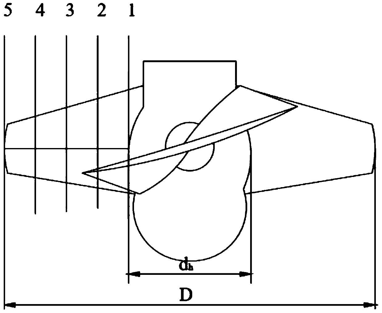
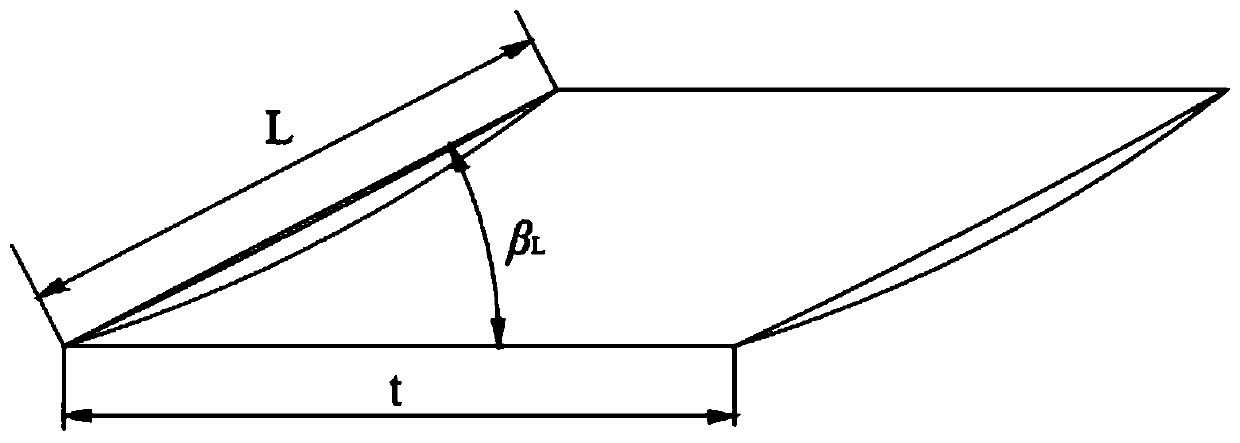
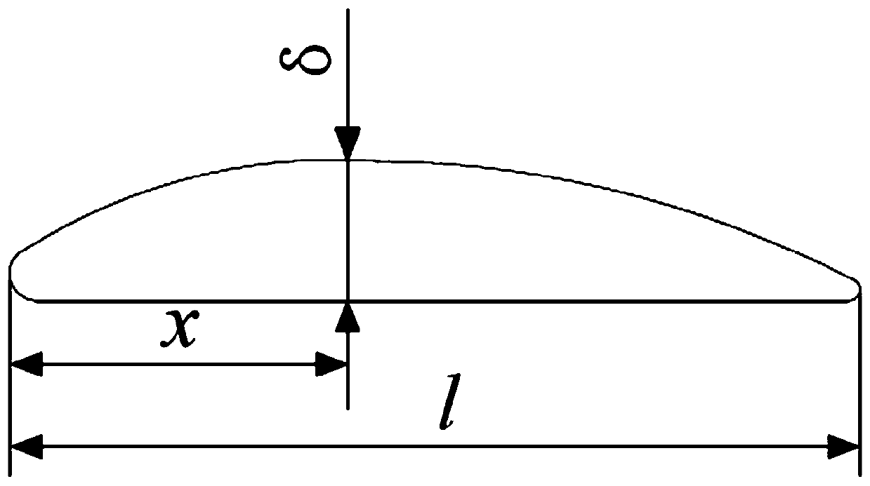

Image

  • A Design Method of Axial Flow Pump Impeller Based on Wheelbase
  • A Design Method of Axial Flow Pump Impeller Based on Wheelbase
  • A Design Method of Axial Flow Pump Impeller Based on Wheelbase

Examples


Embodiment

[0085] Axial flow pump design flow rate Q=0.35m 3 / s, head H=6.72m, speed n=1450r / min, design axial length L 1 = 26mm. The present invention is further described below:

[0086] 1. Determine the airfoil chord length l and blade placement angle β by flow Q, head H, and speed n L , calculated as follows:

[0087] (1) Determine the number of impeller design sections and the number of blades

[0088]

[0089] According to the table below, take the number of impeller sections as 5

[0090] Specific speed n s

n s ≤450

450≤n s ≤800

800≤n s

Number of impeller sections 4 5 6

[0091] According to the following table, take z=4;

[0092] Specific speed n s

0~600 600~850 850~1500 blade number z 3 4 5

[0093] (2) Airfoil chord length l

[0094] The airfoil chord length l of section 5 5

[0095] According to the table below, take a=6;

[0096] blade number z 3 4 5 Correction factor a 3.4~5.8 5...


PUM


Abstract

The invention belongs to the field of fluid machinery design, and discloses a method for designing an impeller of an axial flow pump based on the wheelbase; it includes the following steps: (1) Designing a function L=l×sinβ based on the axial length L of the impeller of the axial flow pump L Based on the given axial flow pump design flow Q, head H, speed n, specific speed n s Design parameters, divide the section at equal intervals from the impeller hub to the outer edge of the impeller, and pass the specific speed n s Determine the number of sections and blades; then determine the airfoil chord length l and blade placement angle β of the axial flow pump impeller L ; (2) Take the airfoil chord length l and the blade placement angle β L As the reference coefficient, determine the impeller diameter D and hub diameter d h , pitch t; (3) choose the 791 airfoil thickness change rule to thicken the blade.

Description

technical field [0001] The invention belongs to the field of fluid machinery design, and in particular relates to a design method of an axial-flow pump impeller based on a wheelbase. Background technique [0002] Pump stations and sluices are important components of water conservancy, environmental protection, urban water supply and drainage, and enterprise water affairs projects. Pumps are irrigation and drainage equipment, and sluices are low-head hydraulic structures that regulate water levels and control flow. The traditional pump gate construction usually adopts the combination of axial flow pump and sluice, that is, a gate is arranged in the middle along the cross section of the river channel, and a water pump is arranged on each side of the gate. The separation design of the pump and the gate of this kind of pump gate leads to the displacement of the traditional pump gate far below the actual needs, and the flood season is often unable to carry out timely and effectiv...

Claims


Application Information

Patent Timeline
Patent Type & Authority Patents(China)
IPC IPC(8): F04D29/18G06F30/17G06F30/20
CPCG06F30/17F04D3/005F04D29/026F04D29/181F05D2240/301G06F2113/08F04D29/18
Inventor 吴贤芳田骁谈明高刘厚林王凯王勇董亮
Owner JIANGSU UNIV
Learn More