Driving protection method, bridge type driving system and motor controller

A motor controller and bridge drive technology, applied in the field of drive, can solve the problems of the upper and lower bridges breaking down the controller, endangering the driving safety of the vehicle, and the direct connection of the upper and lower bridges, so as to ensure the fault protection mechanism, ensure the normal operation state, and avoid The effect of the direct connection between the upper and lower bridges

Active Publication Date: 2020-12-01
HYCET TRANSMISSION SYST (JIANGSU) CO LTD BAODING RES & DEV BRANCH
View PDF20 Cites 0 Cited by
  • Summary
  • Abstract
  • Description
  • Claims
  • Application Information

AI Technical Summary

Problems solved by technology

[0005] 1) The MCU directly controls the drive PWM wave output and shutdown mode for protection, and this drive protection mode is often not timely;
[0006] 2) Protection is carried out through the combination of MCU and hardware logic gate circuit. The hardware logic gate circuit of this drive protection method is often not programmable, and it is not flexible to match with MCU;
[0007] 3) The CPLD is used to protect and control the output and shutdown of the drive PWM wave for protection. Although this kind of protection is fast and timely, once the CPLD has a problem, the safety of the driving system cannot be guaranteed;
[0008] 4) MCU and CPLD are jointly matched and combined for protection, but how to realize the perfect cooperation between MCU and CPLD is very important. Once the cooperation is not good, it will still cause the upper and lower bridges to break through the controller
If there is not a perfect cooperation mechanism between the MCU and CPLD to realize the protection action, it is easy to cause the upper and lower bridges to pass through, thus burning the motor controller and endangering the driving safety of the whole vehicle

Method used


Image

  • Driving protection method, bridge type driving system and motor controller
  • Driving protection method, bridge type driving system and motor controller
  • Driving protection method, bridge type driving system and motor controller

Examples


Embodiment Construction

[0041] It should be noted that, in the case of no conflict, the embodiments and features in the embodiments of the present invention can be combined with each other.

[0042] The present invention will be described in detail below with reference to the drawings and in combination with embodiments.

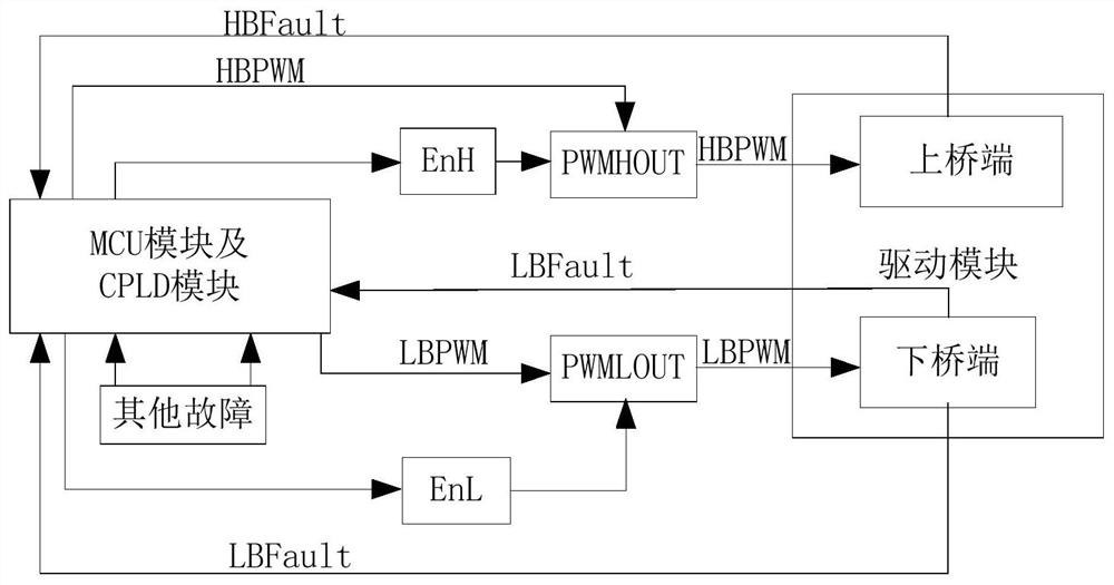
[0043] An embodiment of the present invention provides a driving protection method based on an MCU and a CPLD, which is applied to a bridge driving system with an MCU module and a CPLD module. figure 1 It is a schematic circuit structure diagram of a bridge drive system in an embodiment of the present invention, which includes: an MCU module and a CPLD module; an upper bridge enabling module EnH and a lower bridge enabling module EnL, which are generally controlled by an MCU module and / or a CPLD module , and is used to enable the corresponding signal output module; the upper bridge output module PWMHOUT and the lower bridge output module PWMLOUT respectively enabled by the upper br...


PUM


Abstract

The invention relates to the technical field of driving, and provides a driving protection method based on an MCU and a CPLD, a bridge type driving system and a motor controller. The driving protection method comprises the following steps: controlling the MCU module to respectively send an upper bridge driving signal and a lower bridge driving signal to the upper bridge output module and the CPLDmodule; controlling the CPLD module to send a lower bridge driving signal to the lower bridge output module; configuring an MCU module for controlling the upper bridge enabling module and the lower bridge enabling module; and configuring a CPLD module for controlling both the upper bridge enabling module and the lower bridge enabling module. The method further comprises the steps of establishing communication between the MCU module and the CPLD module, and based on the established communication, executing verification related to the CPLD module at the MCU module end and executing verificationrelated to the MCU module at the CPLD module end. The MCU and the CPLD are perfectly matched, the upper bridge arm and the lower bridge arm of the driving system can be controlled respectively to avoid direct connection of the upper bridge arm and the lower bridge arm, and mutual verification can be performed based on the communication relationship to form redundancy protection.

Description

technical field [0001] The invention relates to the field of drive technology, in particular to a drive protection method based on a microprocessor (Microcontroller Unit, MCU) and a complex programmable logic device (Complex Programmable Logic Device, CPLD), a bridge drive system and a motor controller. Background technique [0002] As we all know, for some electrical equipment, especially the equipment driven by motors, the drive protection technology is very important, and it is an important technical means to ensure the normal operation of the equipment. One of the most widespread applications of drive protection technology is in motor controllers for vehicles. [0003] With the increasing number of new energy vehicles in China and people's higher and higher requirements for safe driving motor technology, the safety control and safety protection mechanism of the motor controller has become the industry development trend, that is, when the vehicle is driving at high speed,...

Claims


Application Information

Patent Timeline
Patent Type & Authority Applications(China)
IPC IPC(8): H02P27/08H02M1/38
CPCH02P27/08H02M1/38
Inventor 张雪拉梅什·库玛·朱钮瑞闫岗郭超
Owner HYCET TRANSMISSION SYST (JIANGSU) CO LTD BAODING RES & DEV BRANCH
Why Eureka
Try Eureka