Nondestructive testing method for residual stress in thermal barrier coating

A thermal barrier coating, residual stress technology, applied in force/torque/work measuring instruments, measuring devices, instruments, etc. The problem of measuring the accurate stress value of thermal barrier coatings, etc., achieves the effect of real-time monitoring of service conditions

Inactive Publication Date: 2019-05-17
NORTHEASTERN UNIV
View PDF6 Cites 1 Cited by
  • Summary
  • Abstract
  • Description
  • Claims
  • Application Information

AI Technical Summary

Problems solved by technology

[0003] Chinese patent CN105486437A discloses a Raman spectroscopy method to detect the stress state at the silicon wafer interface. This method is suitable for detecting the residual stress at the shallow surface of the silicon wafer material, but cannot detect the residual stress at the deeper part of the coating.
The method for detecting residual force disclosed in Chinese patent CN201610128220 needs to use the drilling method to destroy the sample, which cannot meet the requirements of non-destructive testing of

Method used


Image

  • Nondestructive testing method for residual stress in thermal barrier coating
  • Nondestructive testing method for residual stress in thermal barrier coating
  • Nondestructive testing method for residual stress in thermal barrier coating

Examples


Embodiment 1

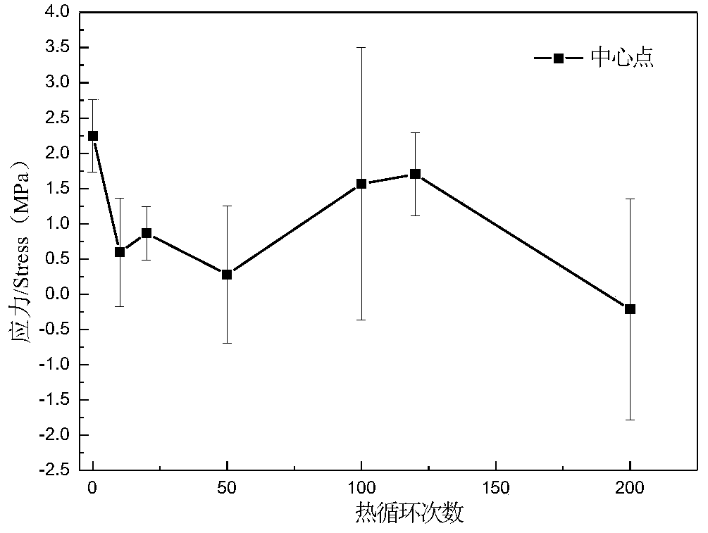
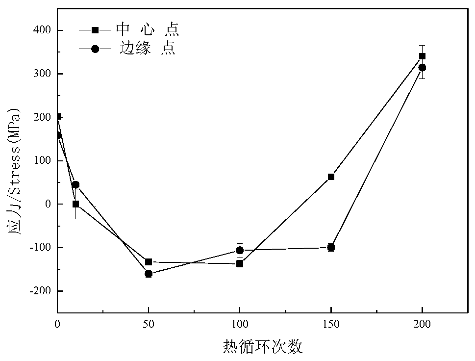
[0022] Place the thermal barrier coating sample horizontally on the sample stage of the Empyrean X-ray diffraction instrument and fix it, so that the normal direction of the sample is consistent with the normal direction of the incident ray, then set the scanning range and measurement method, and measure respectively. X-ray diffraction patterns at different tilt angles. The power of the ceramic X-ray tube is adjusted to 4KW, and the specific frequency of X-ray emission is 1.95×10 18 HZ, the reproducibility of the goniometer is 0.00003 degrees, the controllable minimum step is 0.00003 degrees, the maximum count rate of the PIXcel3D super detector is 120cps, and it is determined according to the relationship between the displacement of the X-ray diffraction peak and the macroscopic stress. Residual stress at a depth of 10 μm in thermal barrier coatings.

Embodiment 2

[0024] Place the thermal barrier coating sample horizontally on the sample stage of the Empyrean X-ray diffraction instrument and fix it, so that the normal direction of the sample is consistent with the normal direction of the incident ray, then set the scanning range and measurement method, and measure respectively. X-ray diffraction patterns at different tilt angles. Adjust the power of the ceramic X-ray tube to 5KW and the specific frequency of X-ray emission to 3×10 18 HZ, the reproducibility of the goniometer is 0.00005 degrees, the minimum controllable step is 0.00007 degrees, and the maximum count rate of the PIXcel3D super detector is 160 cps, which is determined according to the relationship between the displacement of the X-ray diffraction peak and the macroscopic stress. Residual stress in the thermal barrier coating at a maximum depth of 23 μm.

Embodiment 3

[0026] Place the thermal barrier coating sample horizontally on the sample stage of the Empyrean X-ray diffraction instrument and fix it, so that the normal direction of the sample is consistent with the normal direction of the incident ray, then set the scanning range and measurement method, and measure respectively. X-ray diffraction patterns at different tilt angles. Adjust the power of the ceramic X-ray tube to 6KW and the specific frequency of X-ray emission to 9×10 18 HZ, the reproducibility of the goniometer is 0.00006 degrees, the minimum controllable step is 0.00005 degrees, and the maximum count rate of the PIXcel3D super detector is 160 cps, which is determined according to the relationship between the displacement of the X-ray diffraction peak and the macroscopic stress. Residual stress at a depth of 67 μm in thermal barrier coatings.


PUM


Abstract

The invention discloses a nondestructive testing method for residual stress at different depths in a thermal barrier coating, and the method is used for carrying out nondestructive detection on the residual stress at different depths in the thermal barrier coating of an aero-engine by adopting an X-ray diffraction instrument. The method comprises the following steps of firstly, placing and fixinga thermal barrier coating test piece on a sample table, enabling a normal direction of a sample to be consistent with a normal direction of an incident ray, setting the scanning range, adjusting the power of a ceramic X-ray tube, the frequency of the X-ray, the reproducibility of an angular instrument, the controllable minimum step, the maximum counting rate of a PIXcel3D super-energy detector, the sample table direction correction and other factors, emitting the X-ray with the specific frequency, and determining the residual stress at different depths in the thermal barrier coating on the basis of a relation between the displacement of an X-ray diffraction peak and the macroscopic stress. According to the nondestructive testing method for the residual stress in the thermal barrier coatinghas high measurement precision and efficiency and good reproducibility, and is widely applied to nondestructive detection of the residual stress of the thermal barrier coating of the aero-engine.

Description

technical field [0001] The invention relates to a nondestructive testing method for residual stress of thermal barrier coatings, in particular to nondestructive testing of residual stress in thermal barrier coatings used on aero-engines. Background technique [0002] Thermal barrier coating is an important protective coating on aero-engine blades, which is composed of a chromium-containing ceramic layer, a metal bonding layer, and a metal bottom layer. In the process of use, due to the accumulation of thermal stress or residual stress to a certain extent, thermal growth oxidation, cracks and even peeling will occur at the interface of the thermal barrier coating, which brings great hidden dangers to the safety of use. Therefore, it is of great significance to detect the internal stress of thermal barrier coatings in real time. The detection of residual stress in thermal barrier coatings is a very complex problem, mainly because the coating is thin, hard and brittle, which i...

Claims


Application Information

Patent Timeline
IPC IPC(8): G01L5/00
Inventor 王林林小娉杨连威卢晴晴
Owner NORTHEASTERN UNIV
Why Eureka
Try Eureka