Wave arrival angle estimation method based on time modulation array harmonic beam scanning

A beam scanning and time modulation technology, applied in the field of electronic reconnaissance, can solve the problems of occupying large computing resources and high hardware complexity, and achieve the effect of reducing requirements

Active Publication Date: 2019-05-17
XIHUA UNIV
View PDF11 Cites 9 Cited by
  • Summary
  • Abstract
  • Description
  • Claims
  • Application Information

AI Technical Summary

Problems solved by technology

[0005]The above DOA estimation algorithm requires a large number of radio frequency channels, and the hardware complexity is relatively high; in addition, complex mathematical operations are required, which takes up a lot of computing resources

Method used


Image

  • Wave arrival angle estimation method based on time modulation array harmonic beam scanning
  • Wave arrival angle estimation method based on time modulation array harmonic beam scanning
  • Wave arrival angle estimation method based on time modulation array harmonic beam scanning

Examples


Embodiment Construction

[0024] The technical solution provided by the present invention will be described in detail below in conjunction with the accompanying drawings.

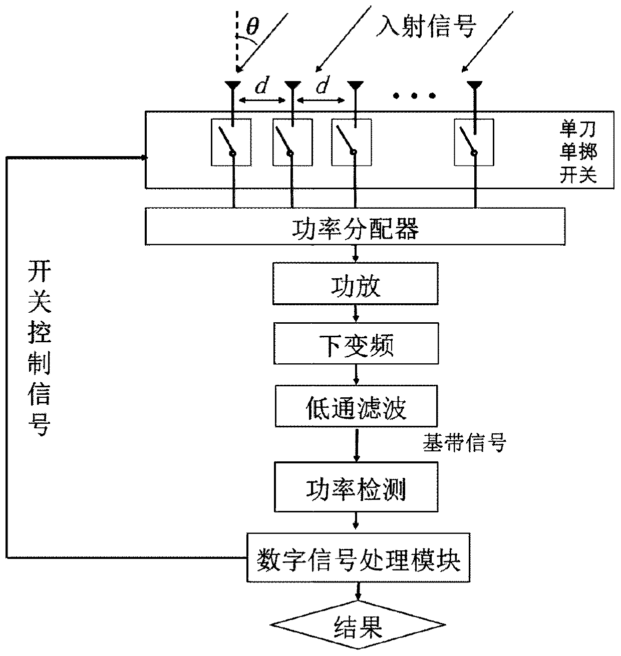
[0025] like figure 1 As shown, a beam scanning direction-of-arrival estimation method based on a time-modulated array includes the following steps:

[0026] Step 1: Configure the number of antenna arrays at the receiving end to be N, with a total of N radio frequency antennas. The array antennas are uniform linear arrays with a half-wavelength spacing, and the time modulation array is in the receiving state.

[0027] The signal received by the nth antenna can be expressed as:

[0028]

[0029] Among them, A 0 is the amplitude of the received signal, F c is the carrier frequency, θ is the incident angle, and λ is the wavelength.

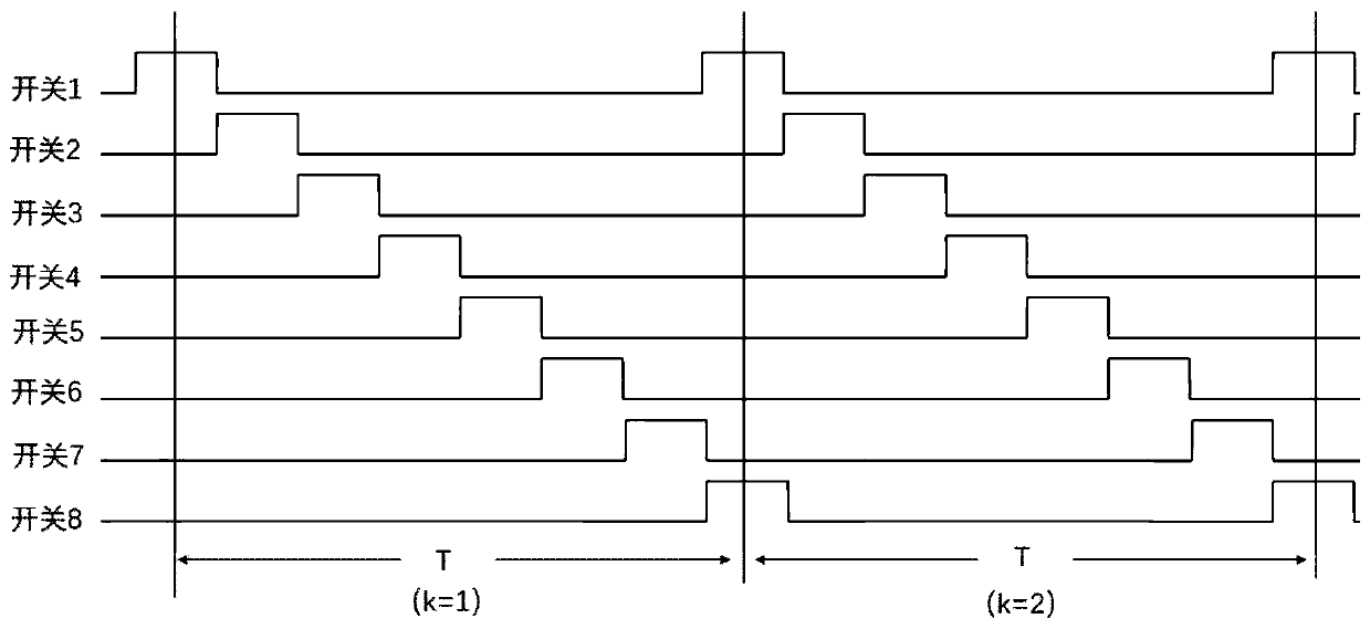
[0030] Step 2: Each array element is connected to a single-pole single-throw switch module. The on-off of the switch is controlled by the digital signal processing module. Through the on-off of the s...


PUM


Abstract

The invention belongs to the field of electronic reconnaissance, and relates to a beam scanning wave arrival direction estimation method based on a time modulation array. The number of receiving end antenna arrays is configured as N, and N radio frequency antennae are included; each array element is connected with a single-pole single-throw switch module, on-off of the switch is controlled througha digital signal processing module, modulated signals are combined into one way through a power distributor, the combined signal is amplified by a power amplifier through a down-conversion module, +2harmonic components are converted down to a base band, and the +2 harmonic components are extracted through a low-pass filter; and a power meter detects the energy output by the low-pass filter in real time and continuously records the output of the power meter, and after T<m> recording for one time, according to the maximum gain direction of an array direction diagram at the maximum output of the power meter, the incident wave direction theta<s> is obtained through table look-up. The beam scanning wave arrival direction estimation method based on the time modulation array omits a high-speeddigital sampling module, reduces the system requirements for digital signal processing chips, and reduces the system requirements for a digital processing module.

Description

technical field [0001] The invention belongs to the field of electronic reconnaissance, and relates to a beam scanning direction-of-arrival estimation method based on a time modulation array. Background technique [0002] The research on the estimation algorithm of Direction of Arrival (DOA) is one of the key problems in array signal processing, and the main research task is how to estimate the DOA of the signal from the background noise. Common direction finding methods include amplitude ratio method, interferometer direction finding method, time difference of arrival method, Doppler direction finding method, spatial spectrum direction finding method and so on. [0003] The working principle of the amplitude comparison type direction finding system is to measure the direction of the incoming wave based on the difference in the amplitude of the incoming wave received from different directions by using the direction characteristic of the direction finding antenna array or the...

Claims


Application Information

Patent Timeline
Patent Type & Authority Applications(China)
IPC IPC(8): G01S3/16
CPCY02D30/70
Inventor 张学军白琳陈群
Owner XIHUA UNIV
Why Eureka
Try Eureka