
An automatic molding device and method for a charging plug shell

A charging plug and forming device technology, applied in the field of automatic forming devices for charging plug shells, can solve problems such as low precision, low fixture circulation efficiency, and low efficiency, so as to improve efficiency and precision, facilitate integrated processing, and improve The effect of work efficiency

Active Publication Date: 2020-07-31
东莞市庚威实业有限公司
View PDF4 Cites 0 Cited by
  • Summary
  • Abstract
  • Description
  • Claims
  • Application Information

AI Technical Summary

Problems solved by technology

Most of the existing production methods are semi-automated and assembled manually. The shortcomings of the existing technology are: 1. Slow feeding of the substrate, low efficiency, and low precision; 2. Low circulation efficiency and poor precision of the fixture; 3. . It is difficult to clamp the material on the clamping shell, and the efficiency is low; 4. The rivet column parts are small, difficult to clamp, variable, and low in assembly accuracy; 5. The separation between the fixtures of the workpiece is complicated, and the tooling structure is complicated

Method used


Image

  • An automatic molding device and method for a charging plug shell
  • An automatic molding device and method for a charging plug shell
  • An automatic molding device and method for a charging plug shell

Examples


Embodiment Construction

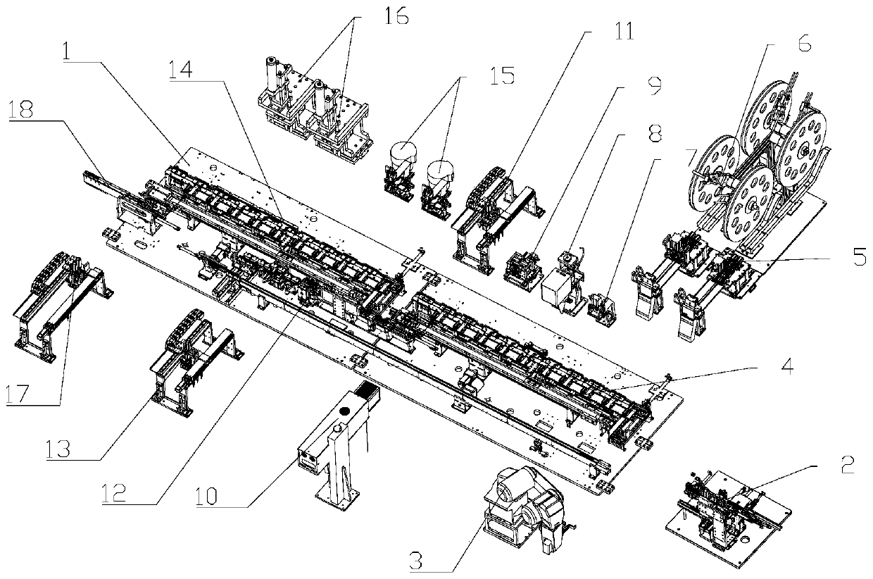
[0042] like figure 1 As shown, the described charging plug automatic assembly equipment includes a frame 1 and a substrate feeding device 2 installed on the frame 1, a mechanical arm handling device 3, a clamping fixture circulation device 4, and a lower clamping shell feeding device. Device 5, upper shell feeding device 6, shell pressing device 7, shell detection device 8, shell bending device 9, shell welding device 10, first conveying device 11, base jig reflow device 12, The second conveying device 13, the riveting fixture circulation device 14, the riveting column feeding device 15, the riveting column pressing device 16, the third conveying device 17 and the product unloading device 18; the folder bending device 9 is the charging plug shell automatic molding device.

[0043]The substrate feeding device 2 is used to put the substrate into the substrate jig, and feed the substrate together with the substrate jig; the mechanical arm handling device 3 is connected with the ...


PUM


Abstract

The present invention relates to the field of charging device production and manufacturing, especially to an automatic formation device and method of a charging plug housing. The automatic formation device comprises an eighteenth base, a 28th cylinder, a mounting base, a 29th cylinder, a bottom plate, a cover plate, guide pillars, stop blocks, a bending mechanism, drive skew plates and end portionbending plates; the row of end portion bending plates are fixed and clamped by the bottom plate and the cover plate, inclined angles are formed at two sides of one ends of the end portion bending plates, the bending mechanism is longitudinally symmetrically arranged, the bending mechanism comprises a roller slot strip, mounting plates and bending claws; the stop blocks are fixedly arranged on thecover plate to control the pressure force; the upper end of the roller slot strip is connected with a roller, the roller slot strip is in movement matching with the eighteenth base, the roller slot strip is fixed with the mounting plates, and the bending claws are fixedly arranged on the mounting plates. The automatic formation device of the charging plug housing makes workpieces uniformly forcedthrough synchronous stretching of the bending pieces with no need for other auxiliary clamping devices, only needs one drive power, and is convenient and efficient.

Description

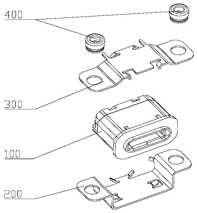
technical field [0001] The invention relates to the field of charging equipment production and manufacturing, in particular to an automatic molding device and method for a charging plug shell. Background technique [0002] The charging plug is one of the components connected to the electrical circuit, which realizes the transmission of signals between two devices, such as the wiring structure of the telephone line, the wiring structure of the network line, etc., mainly inserting a signal transmission line into the electronic connector with fixed specifications, the structure Generally divided into one male and one female. The connecting female head is structurally composed of a base body, a shell and a rivet post, the shell is used for the base body, and the base body is used for wiring. Most of the existing production methods are semi-automated and assembled manually. The shortcomings of the existing technology are: 1. Slow feeding of the substrate, low efficiency, and low...

Claims


Application Information

Patent Timeline
Patent Type & Authority Patents(China)
IPC IPC(8): H01R43/18H01R43/20
Inventor 李琼陈荣乾李柯
Owner 东莞市庚威实业有限公司
Learn More