

Air bag driving sleeving and binding device
A driving type and airbag technology, applied in the field of medical devices, can solve the problems of complex operation, complex structure and process, slippage of traction wire, etc., and achieve the effect of simple and fast installation, simplified operation procedure, and easy and simple operation
- Summary
- Abstract
- Description
- Claims
- Application Information
AI Technical Summary
Problems solved by technology
Method used
Image

Examples
Embodiment Construction
[0040] The following embodiments will further illustrate the present invention in conjunction with the accompanying drawings.
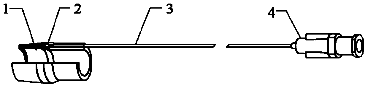
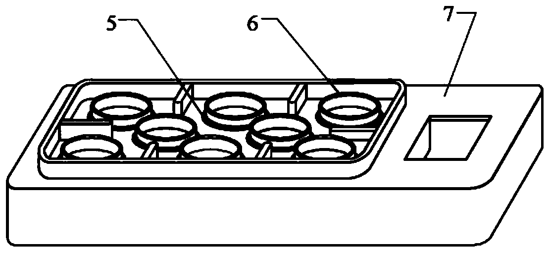
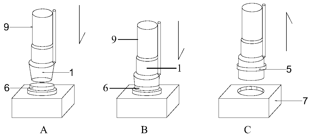
[0041] see Figure 1~5 , the embodiment of the present invention is provided with a ligation inner tube 1, a ligation outer tube 2, a connecting catheter 3, a syringe interface 4, a ligation ring 5, a ligation ring bracket cylinder 6, a ligation ring mounting plate 7, a syringe 8 and an inner mirror 9; the ligation ring 5 is set on the outermost front part of the ligation inner tube 1, the ligation outer tube 2 is wrapped on the outer side of the ligation inner tube 1, and the front part of the ligation outer tube 2 is thinner. Normally, it is in a contracted state, and the ligation outer tube 2 is closely attached to the outer surface of the ligation inner tube 1. The front end of the ligation outer tube 2 is open or closed, and the rear part of the ligation outer tube 2 is continuously thickened to form a The connecting pipe socketed at the front e...
PUM
 Abstract
Description
Claims
Application Information