
Smashing and air feeding integrated machine

An all-in-one, air-delivery technology, applied in agricultural machinery and implements, cutting equipment, grain processing, etc., can solve the problems such as the inability of the hammer wing structure design to provide wind power, the inability to achieve automatic feeding, and the impact on material output, so as to improve the material output. The effect of crushing efficiency, compact structure design and high crushing efficiency

Pending Publication Date: 2019-05-21
济南庆硕环保设备有限公司
View PDF1 Cites 2 Cited by
  • Summary
  • Abstract
  • Description
  • Claims
  • Application Information

AI Technical Summary

Problems solved by technology

There are disadvantages of high cost, high energy consumption and large occupied area for crushing in the above way, so it is necessary to improve it
[0004] In order to reduce the cost of crushing equipment, save floor space, improve production efficiency, and make the product design more reasonable and tend to be perfect, various attempts have been made in the prior art to make the overall structure of the crushing equipment more reasonable, but there are always some unresolved problems. As expected, for example, the Chinese patent invention CN1045534A discloses a kind of wood powder pulverizer. The core of this technical solution is to install hammer blade wings on the hammer blades, which can generate centrifugal wind force to blow out the hammered materials. To a certain extent, the concept of the integrated design of the pulverizer and the blower has been realized, but there are certain deficiencies in the structural design of this technical scheme, such as the structural design, design position and installation angle of the hammer blade cannot provide sufficient wind force, which in turn affects the material output, let alone Realize automatic feeding

Method used


Image

  • Smashing and air feeding integrated machine
  • Smashing and air feeding integrated machine
  • Smashing and air feeding integrated machine

Examples


Embodiment Construction

[0032] In order to explain the overall concept of the present invention more clearly, the following will be described in detail by way of examples in conjunction with the accompanying drawings.

[0033] In the following description, many specific details are set forth in order to fully understand the present invention. However, the present invention can also be implemented in other ways different from those described here. Therefore, the protection scope of the present invention is not limited by the specific details disclosed below. EXAMPLE LIMITATIONS.

[0034] In addition, in the description of the present invention, it should be understood that the orientation or positional relationship indicated by the terms "circumferential direction", "lower end", "upper", "side wall" etc. is based on the orientation or positional relationship shown in the drawings , is only for the convenience of describing the present invention and simplifying the description, but does not indicate or...


PUM


Abstract

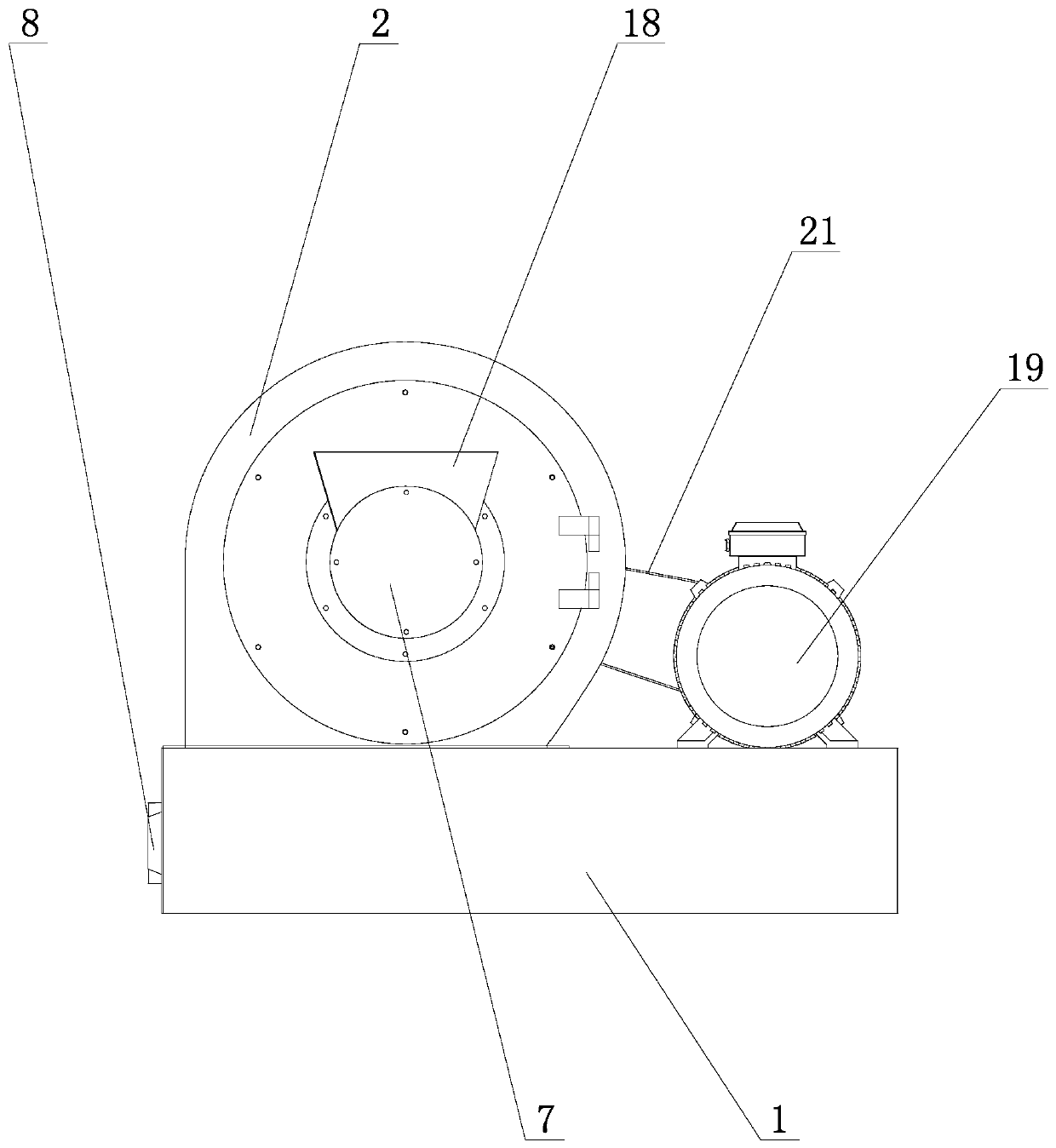
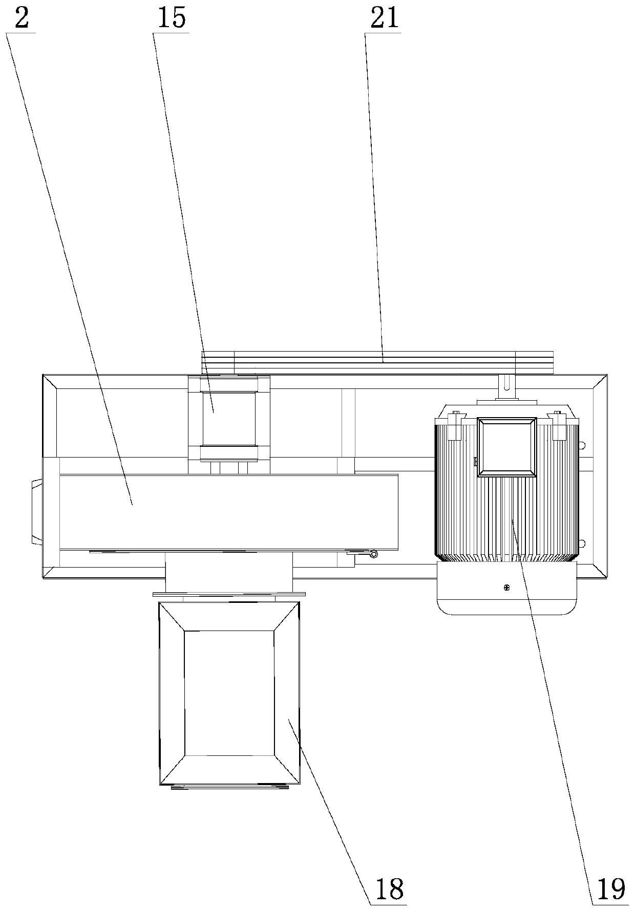
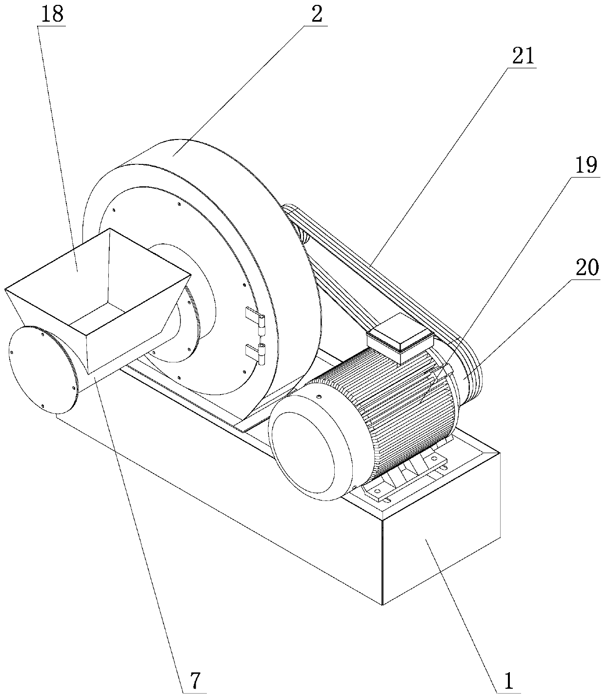
The invention relates to a smashing and air feeding integrated machine. The smashing and air feeding integrated machine comprises a base; a driving unit and a smashing and air feeding unit are correspondingly arranged on the base; the driving unit is connected with the smashing and air feeding unit; the smashing and air feeding unit comprises a smashing chamber; a rotor disk is arranged in the smashing chamber; the rotor disk is connected with the driving unit through a driving shaft; a plurality of hammer sheets for smashing materials, and a plurality of blades for carrying out air feeding onthe materials are correspondingly arranged on the rotor disk; a feeding channel communicating with the smashing chamber is formed in the side wall of one side of the smashing chamber; the other sideof the smashing chamber is connected with the driving unit; a discharge channel communicating with the smashing chamber is formed in the smashing chamber; and a screen is arranged between the discharge channel and the rotor disk. The smashing and air feeding integrated machine has the advantages that the feeding and smashing effects are achieved by one equipment, the air feeding ability is high, afloor area is small, the complete machine is compact in structural design, the cost is low, and the smashing efficiency is high.

Description

technical field [0001] The invention relates to the technical field of crushing equipment, in particular to a crushing and blowing integrated machine capable of crushing brittle materials such as wood chips and straws. Background technique [0002] The pulverizer is a machine that crushes large-sized solid raw materials to the required size. It is widely used in mining, building material crushing and other fields. The hammer mill is an important type of pulverizer, which mainly uses the impact principle to impact and pulverize materials, and is suitable for pulverizing brittle materials. [0003] As the country vigorously promotes energy saving and environmental protection, all walks of life are actively influencing the government's call to save and reuse resources, such as recycling and reprocessing wood dust generated in furniture production as fuel, and recycling and processing crop straw as biological feed. The recycling and processing of brittle materials must go throu...

Claims


Application Information

Patent Timeline
IPC IPC(8): B02C13/13B02C13/26B02C13/28B02C13/286B02C13/288B02C13/30B27L11/06A01F29/00
Inventor 韩松松杨玉芹
Owner 济南庆硕环保设备有限公司
Learn More