A CNC gear hobbing machine

A technology of gear hobbing machine and main engine, which is applied in the direction of gear cutting machine, gear teeth, mechanical equipment, etc. It can solve the problems of uncompact base structure, large base area, and poor shock resistance, and achieve excellent shock resistance, large driving torque, and The effect of high stiffness

Active Publication Date: 2018-07-10
ZHEJIANG RICHUANG MECHANICAL & ELECTRICAL TECH
View PDF10 Cites 0 Cited by
  • Summary
  • Abstract
  • Description
  • Claims
  • Application Information

AI Technical Summary

Problems solved by technology

[0004] Although the base of the main machine of the existing CNC gear hobbing machine is not a functional part for direct cutting, it is the connecting body of the two parts of the machine tool slide plate and the tool holder assembly. Stable performance and good effect in high-precision and high-strength cutting, the base structure in the prior art is not compact, the base occupies a large area, its rigidity is poor, and the shock resistance is not good

Method used


Image

  • A CNC gear hobbing machine
  • A CNC gear hobbing machine
  • A CNC gear hobbing machine

Examples


Embodiment Construction

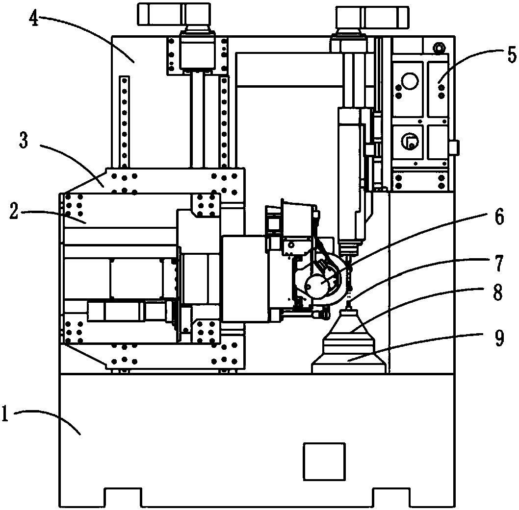
[0046] see attached Figure 1~17 , A CNC gear hobbing machine, the main machine is in a vertical layout, the main machine includes a bed 1, a base 2, a slide plate 3, a column 4, a tailstock 5, a tool rest 6, a workpiece 7, a workpiece fixture 8 and a workbench 9, The column 4 and the bed 1 are in an L-shaped rigid connection structure; the base 2, the slide plate 3, the tailstock 5, and the tool rest 6 are respectively installed on the column 4, and are arranged in a square shape on the column; the base The right side of 2 is connected with the tool rest 6 through the outer casing 10; the nut bracket on the back side of the base 2 is connected with the ball screw and the nut on the slide plate 3, and the rotation of the ball screw drives the base 2 and the tool rest 6 to make a horizontal direction. move; realize the radial feed of the X-axis of the machine tool; the slide plate 3 moves vertically up and down on the column 4 to realize the vertical feed of the Z-axis of the m...


PUM


Abstract

The invention relates to a numerical control gear hobbing machine. A stand column and a machine body are rigidly connected in an L form; a base, a slide plate, a tail base and a cutter frame are arranged on the stand column in a similar n form; the right side of the base is connected with the cutter frame through a cover; the back side of the base is matched and connected with the slide plate; the slide plate drives the base and the cutter frame to horizontally move to realize X-directional feeding of a machine tool; the slide plate vertically moves on the stand column to realize Z-directional feeding of the machine tool; the tail base includes a base body fixed on the stand column; a tip slide base module is slidingly mounted on the base body in the longitudinal direction; a worktable is mounted on the machine body, and is provided with a workpiece fixture capable of positioning a workpiece; the workpiece is pushed tightly or loosened by a tip on the tip slide base module; and an indexing main shaft of the cutter frame is connected with the cover, and rotates through a driving device to drive rotation of a hobbing tool on the cutter frame for cutting the workpiece. The stand column and the worktable do not move; the work of the machine tool is realized by matching movements of the base, the slide plate, the tail base and the cutter frame; and the numerical control gear hobbing machine is compact in structure and high in rigidity.

Description

technical field [0001] The invention relates to the field of gear hobbing machine equipment, in particular to a main engine of a dry type or wet type ultra-precision ultra-high-speed numerically controlled gear hobbing machine. Background technique [0002] The main engine of the existing CNC gear hobbing machine is designed to move either the column or the table. There is a rear column, and the top tailstock body is fixed on the rear column. Part of the connection is not tight, the overall rigidity is poor, and the rotation accuracy of the top cannot be adjusted, the top is unstable during the movement of the top, the rigidity of the top is not good, and the entire device structure is not compact. [0003] At the same time, the existing structure has a long transmission chain between the hob and the worktable, and the indexing accuracy of the machine tool depends on the accuracy of the transmission chain. The gap between the drive elements in the drive chain reduces drive ...

Claims


Application Information

Patent Timeline
Patent Type & Authority Patents(China)
IPC IPC(8): B23F23/00B23F23/06B23F23/12B23Q1/01B23Q1/25B23Q5/40B23B33/00B23B21/00B23Q11/12B23Q11/10B23Q11/00
CPCB23B33/00B23F23/00B23F23/06B23F23/12B23Q1/015B23Q1/25B23Q5/40B23Q11/00B23Q11/0042B23Q11/10B23Q11/127
Inventor 陶新根闵中华周伟强冯剑
Owner ZHEJIANG RICHUANG MECHANICAL & ELECTRICAL TECH
Why Eureka
Try Eureka