Electronic garbage recovery treatment equipment

A technology of recycling and electronic waste, applied in the direction of electronic waste recycling, grain processing, recycling technology, etc., can solve the problems of high feeding port, waste of physical strength, unfavorable work efficiency, etc., to achieve unbreakable, convenient and labor-saving feeding, and convenient follow-up The effect of treatment

Inactive Publication Date: 2019-05-21
湖南聚义岩科技有限公司
View PDF0 Cites 14 Cited by
  • Summary
  • Abstract
  • Description
  • Claims
  • Application Information

AI Technical Summary

Problems solved by technology

[0003] The feeding port of the electronic waste recycling and processing equipment is relatively high. When feeding, the staff often need to carry the electronic waste to the feeding port and dump it, which is a waste of energy and is not conducive to improving the overall work efficiency; when the electronic waste is crushed, it is often only broken once. , some e-waste is incompletely broken, which is not conducive to subsequent processing

Method used


Image

  • Electronic garbage recovery treatment equipment
  • Electronic garbage recovery treatment equipment
  • Electronic garbage recovery treatment equipment

Examples


Embodiment 1

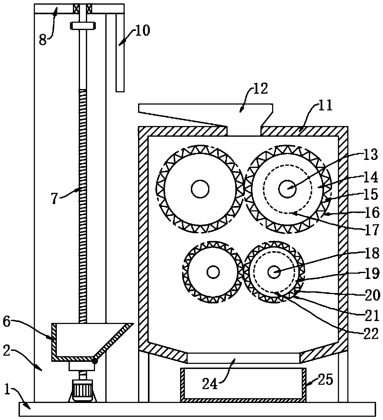
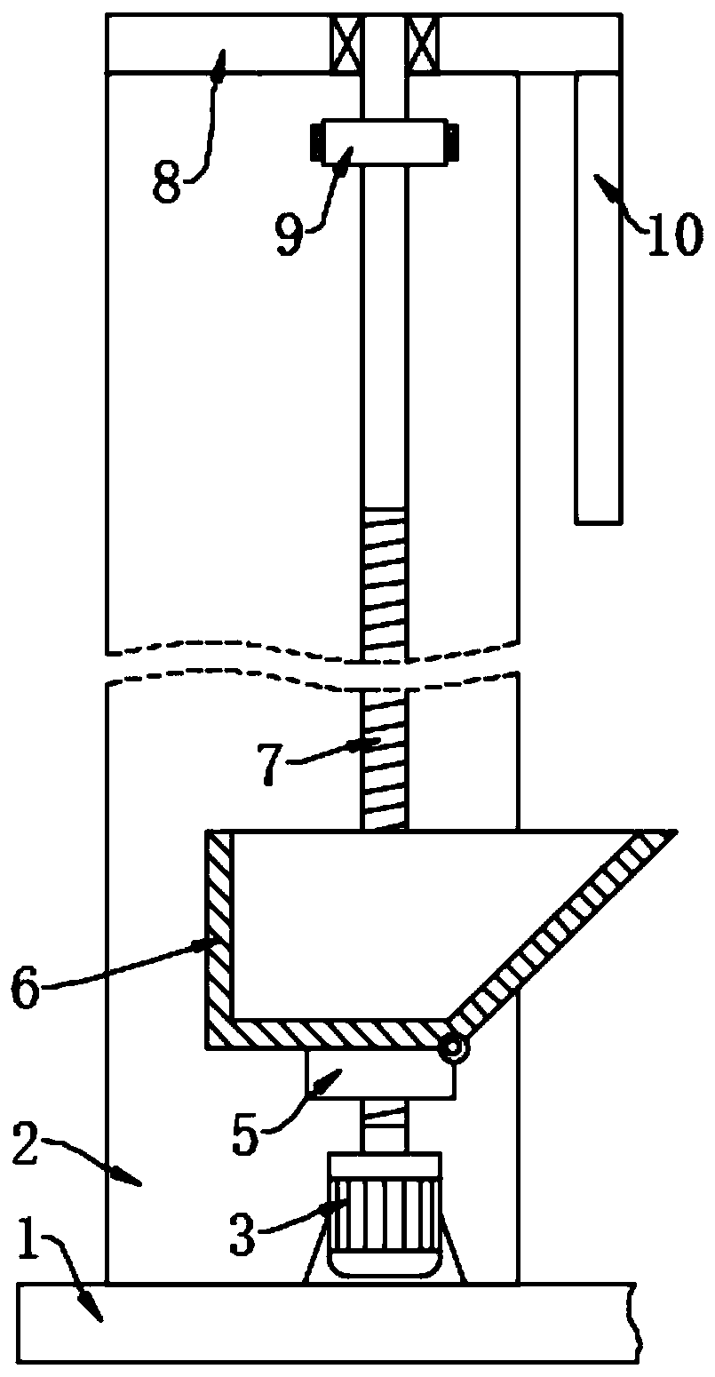
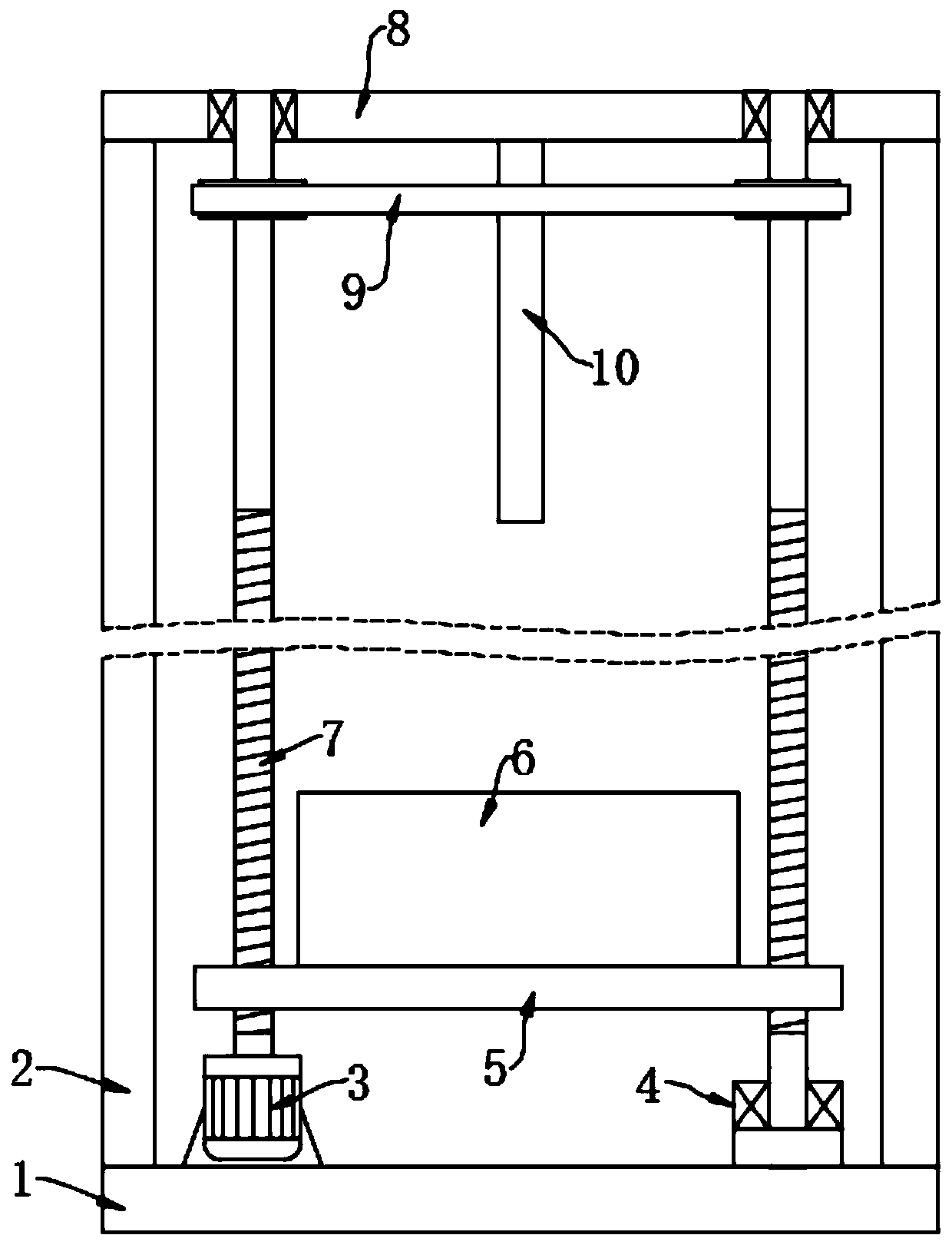
[0027] see Figure 1~4 , in an embodiment of the present invention, an electronic waste recycling and processing device includes a base 1, the top of the base 1 is fixed with a crushing box 11 through a bracket, the top of the crushing box 11 is provided with a feeding hopper 12, and the feeding hopper 12 extends to The upper left side of the crushing box 11 is convenient for adding electronic waste from the left side; the front and rear directions in the crushing box 11 are provided with two first rotating shafts 13 on the left and right, and the left and right first rotating shafts 13 are respectively connected to the front and rear walls of the crushing box 11 in rotation. The rotating shaft 13 located in the crushing box 11 is fixedly equipped with a first crushing roller 14, and the side wall of the first crushing roller 14 is evenly provided with a number of first crushing teeth 15; Two rotating shafts 18, the second rotating shaft 18 is located below the first rotating ...

Embodiment 2

[0030] see Figure 5 , on the basis of Example 1, the bottom of the crushing box 11 is fixedly provided with a screen 26, the screen 26 is inclined downward to the right, and the right end of the screen 26 is fixedly connected with a discharge chute 27, and the discharge chute 27 passes through the The right wall of the crushing box 11 extends to the outside of the crushing box 11; a vibration motor 28 is fixedly installed at the bottom of the screen 26, and the vibration motor 28 drives the screen 26 to vibrate to screen the electronic waste fragments falling on the screen 26. The plastic in the garbage is easily broken and falls through the sieve mesh 26, while the metal in the electronic waste has better toughness and is not easy to break, so it slides to the right, which is beneficial to the classification of the electronic waste and facilitates subsequent processing.


PUM


Abstract

The invention discloses electronic garbage recovery treatment equipment, and relates to the technical field of electronic garbage treatment. The electronic garbage recovery treatment equipment comprises a base; a crushing box is fixedly arranged at the top of the base through a bracket; left and right first rotating shafts are arranged in the crushing box in the front-back direction, and are rotationally connected with the front and back walls of the crushing box; first crushing rollers are fixedly mounted on the parts, positioned in the crushing box, of the left and right first rotating shafts; multiple first crushing teeth are uniformly arranged on the side walls of the first crushing rollers; left and right second rotating shafts are arranged in the crushing box in the front-back direction, and are rotationally connected with the front and back walls of the crushing box; second crushing rollers are fixedly mounted on the parts, positioned in the crushing box, of the left and right second rotating shafts; and multiple second crushing teeth are uniformly arranged on the side walls of the second crushing rollers. Through opposite rotation of the first crushing rollers, waste electronic garbage is primarily crushed; and through opposite rotation of the second crushing rollers, the waste electronic garbage is crushed again, so that the electronic garbage is fully crushed.

Description

technical field [0001] The invention relates to the technical field of electronic waste treatment, in particular to electronic waste recycling and processing equipment. Background technique [0002] Refers to electrical appliances or electronic equipment that have been discarded and no longer used, mainly including household appliances such as refrigerators, air conditioners, washing machines, and televisions, and communication electronic products such as computers, and other electronic technology obsolete products. The materials used in electronic products are generally of high value. After electronic products are damaged, electronic products will be recycled. The existing recycling method is mainly to disassemble electronic products. Except for some components that can be directly recycled, the rest are crushed , and then extract useful elements from the crushed electronic fragments. [0003] The feeding port of the electronic waste recycling and processing equipment is r...

Claims


Application Information

Patent Timeline
Patent Type & Authority Applications(China)
IPC IPC(8): B09B3/00B09B5/00B02C4/08B02C4/28B02C4/30B02C4/42B02C23/02B02C23/10B07B1/42B07B1/46
CPCY02W30/82
Inventor 康高阳蔡正大陈勇
Owner 湖南聚义岩科技有限公司
Why Eureka
Try Eureka