
Sheet workpiece punching technology

A workpiece and sheet technology, applied in the field of sheet workpiece blanking process, can solve the problems of large drop height and workpiece deformation, and achieve the effect of small drop height, preventing workpiece edge deformation and reducing drop height.

Active Publication Date: 2019-05-21
安徽中瑞机床制造有限公司
View PDF13 Cites 0 Cited by
  • Summary
  • Abstract
  • Description
  • Claims
  • Application Information

AI Technical Summary

Problems solved by technology

[0006] Aiming at the problem that the existing stamping process uses a punching rod to beat the material, the workpiece falls out of the mold cavity, and the falling height is large, and the workpiece is easily deformed when it hits the lower die after falling. The invention provides a blanking process for thin plate workpieces. The material is punched into a workpiece. The punching machine includes a punching machine body, a mold base, an upper mold assembly and a lower mold. There is a relief groove in the middle of the upper mold assembly, and an oil cylinder feeding device is installed at the bottom of the mold base. The oil cylinder feeding device is located in the relief In the groove, the upper die assembly is equipped with a floating ejector assembly that can float up and down. The floating ejector assembly is pushed by the oil cylinder feeding device, and the workpiece is ejected from the upper die assembly at the same time as the upper die assembly returns, and the workpiece falls. The height is small, it will not cause deformation of the workpiece, which greatly improves the punching quality

Method used


Image

  • Sheet workpiece punching technology
  • Sheet workpiece punching technology
  • Sheet workpiece punching technology

Examples


Embodiment 1

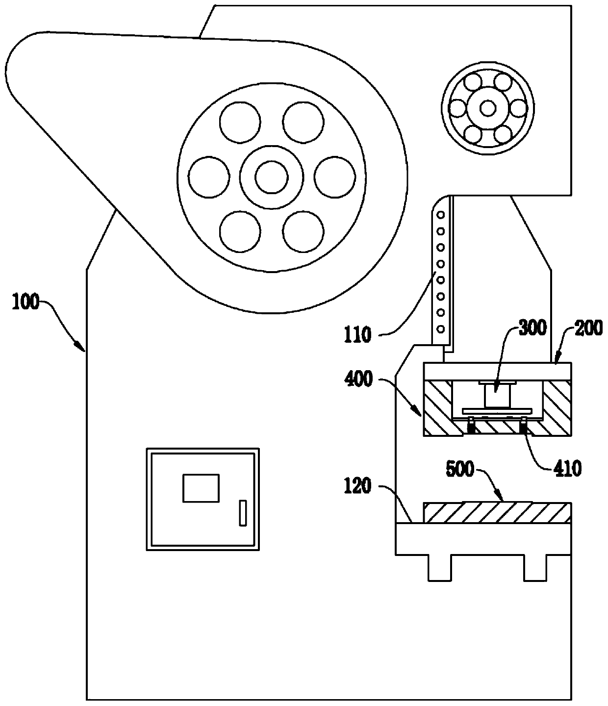
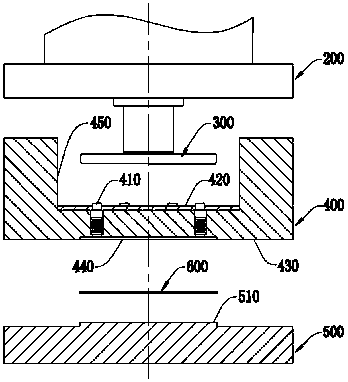
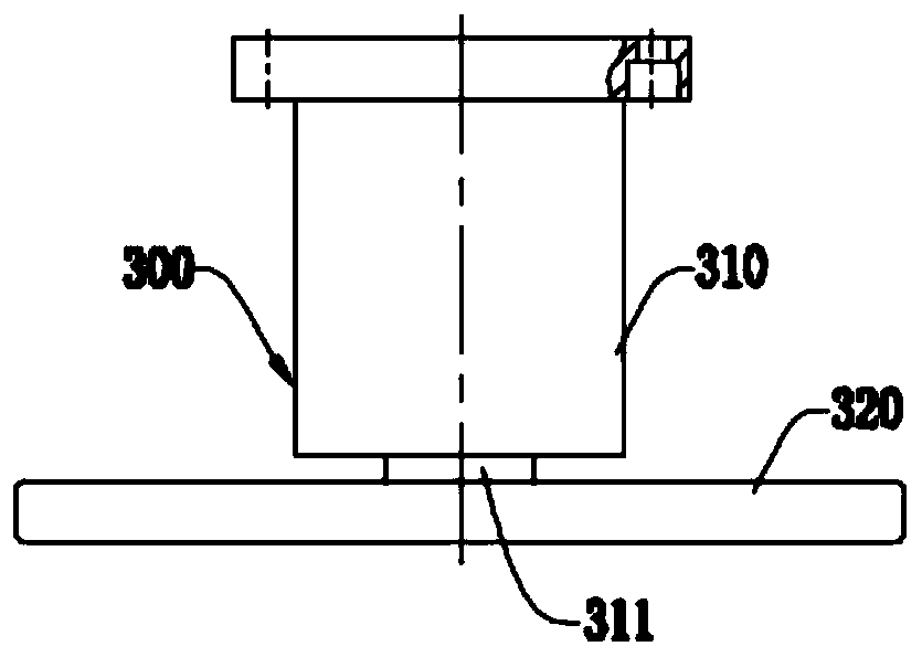
[0050] A blanking process for thin plate workpieces, using a punching machine to blank materials into workpieces 600, such as figure 1 , 2 As shown, the punch press includes a punch body 100, a die base 200, an upper die assembly 400 and a lower die 500, the front side of the punch body 100 is provided with a slide rail 110, and the die base 200 is slidably connected to the slide rail 110, and is connected with the power unit arranged in the punch body 100, and is driven by the punch body 100 to move up and down along the slide rail 110; the upper die assembly 400 is fixed on the bottom of the die base 200, and It is detachably connected with the mold base 200 by bolts; the lower mold 500 is fixed on the mounting platform 120 on the front side of the punch body 100, and cooperates with the upper mold assembly 400 up and down; the bottom of the mold base 200 is provided with The oil cylinder feeding device 300, the middle part of the upper mold assembly 400 is provided with a ...

Embodiment 2

[0065] A sheet blanking process of this embodiment is basically the same as that of Embodiment 1, the difference and improvement is that the oil cylinder feeding device 300 starts within 0.5 seconds after the upper die assembly 400 starts to return, and the oil cylinder After the feeding device 300 is started, the workpiece 600 is ejected out of the upper mold assembly 400. At this time, the upper mold assembly 400 rises within 6 cm, and the workpiece 600 falls at a lower height, which can prevent the workpiece from falling behind due to the excessive rise of the upper mold assembly. Impact deformation.

Embodiment 3

[0067] A blanking process for thin plate workpieces in this embodiment is basically the same as in Embodiment 1 or 2, the difference and improvement is that the length of the floating ejector rod assembly 410 moving down and extending into the mold core groove 440 is at least Workpiece 600 thickness.

[0068] When the depth of the core groove 440 is greater than the thickness of the workpiece 600, the floating ejector rod assembly 410 needs to extend from the bottom of the core groove 440 to the notch of the core groove 440 to eject the workpiece 600 from the core groove 440. When the floating ejector rod assembly 410 moves down, the length extending into the mold core groove 440 is greater than the thickness of the workpiece 600 .

[0069] When the depth of the core groove 440 is just equal to the thickness of the workpiece 600, the floating ejector rod assembly 410 is pushed down by the cylinder beating device 300, and the length extending into the core groove 440 is the sam...


PUM

PropertyMeasurementUnit
thicknessaaaaaaaaaa
thicknessaaaaaaaaaa

Abstract

The invention discloses a sheet workpiece punching technology, and belongs to the technical field of punching technologies. A punch is utilized for punching materials into a workpiece and comprises apunch body, a die base, an upper die assembly and a lower die, and the die base is in sliding connection to a sliding rail on the front side of the punch body. The upper die assembly is fixed to the bottom of the die base. The lower die is fixed to an installing table on the front side of the punch body and matched with the upper die assembly up and down. An oil cylinder material beating device isarranged at the bottom of the die base and located in an avoiding groove in the middle portion of the upper die assembly. A floating ejector rod assembly capable of floating up and down is arranged in the upper die assembly, the oil cylinder material beating device jacks the upper end of the floating ejector rod assembly, and the lower end of the floating ejector rod assembly stretches into a diecore groove in the bottom of the upper die assembly. The oil cylinder material beating device arranged below the die base in the punch is utilized for pushing the floating ejector rod assembly arranged in the upper die assembly, when the upper die assembly of the punch returns, the workpiece disengages from the upper die assembly, the falling height of the workpiece is small, deformation is avoided, and the punching quality is greatly improved.

Description

technical field [0001] The invention relates to the technical field of punching technology, in particular to a blanking technology for thin plate workpieces. Background technique [0002] Punching is a stamping process that uses a die to separate part of the material or process part from another part of the material, process (process) part or waste. Blanking is a general term for the separation processes such as shearing, blanking, punching, punching, notching, sectioning, chiseling, edge trimming, tongue cutting, cutting, and trimming, and it accounts for the largest proportion in stamping production. In the blanking process, the sheet metal is sheared and deformed along a certain contour line by using the cutting edge of the die and separated. Except for the metal near the shear contour line, the sheet itself does not produce plastic deformation, so it is punched by a flat plate. The processed parts are still in a flat shape. [0003] Existing stamping equipment generall...

Claims


Application Information

Patent Timeline
Patent Type & Authority Applications(China)
IPC IPC(8): B21D28/02B21D45/04
Inventor 夏尧林戴庆
Owner 安徽中瑞机床制造有限公司
Features
  • Generate Ideas
  • Intellectual Property
  • Life Sciences
  • Materials
  • Tech Scout
  • Unparalleled Data Quality
  • Higher Quality Content
  • 60% Fewer Hallucinations
Learn More