Flat tube pushing and limiting device for threading machine

A limit device and belt threading machine technology, which is applied in the field of belt threading machines, can solve the problems of poor shape of the intercooler tube nozzle, high scrap rate, and many waste products of the intercooler tube assembly, so as to improve the success rate of belt threading , improve the qualified rate, and the effect of simple structure

Inactive Publication Date: 2019-05-21
SHANDONG XINHEYUAN HEAT TRANSFERRING TECH
View PDF7 Cites 0 Cited by
  • Summary
  • Abstract
  • Description
  • Claims
  • Application Information

AI Technical Summary

Problems solved by technology

[0003] On the one hand, in the work of the modern system, the spoiler belt (fin) of the intercooler of the automobile adopts the flat tube type, and several flat tubes are placed in the lower plate. Due to the action of gravity, the upper flat tube forms pressure on the bottom flat tube, The flat tube at the bottom is deformed, and when the fins are connected to the intercooler tube (that is, the flat tube), because the fins are too thin and the shape of the intercooler tube opening is poor, the fins are prone to damage during the piercing, resulting in intercooler There are many waste products in the pipe assembly, which affects the efficiency of system work and belt threading
[0004] On the other hand, when the flat tube heat exchanger is assembled, several flat tubes fall into the glide groove of the lower plate of the intercooler tube. , the bottom of the next flat tube will be rubbed, the side wall of the flat tube will be damaged, and the scrap rate is high
The traditional method is to install felt on the pusher plate to reduce friction, but after the felt is used for a long time, there will be impurities, such as dust or aluminum chips, which will pollute the pusher plate
At the same time, it is easy to fall off after long-term use and requires frequent repairs, causing great trouble to users.

Method used


Image

  • Flat tube pushing and limiting device for threading machine
  • Flat tube pushing and limiting device for threading machine
  • Flat tube pushing and limiting device for threading machine

Examples


Embodiment Construction

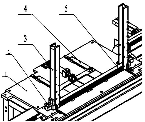
[0029] As shown in the figure, the present invention is a flat tube pushing and limiting device for a belt threading machine. The length of the flat tube is 686mm, and the length of the fins (that is, the spoiler belt) is 342mm, including

[0030] A frame, on which a workbench 1 is arranged;

[0031] The flat tube storage unit is vertically fixed on the workbench 1 for storing the flat tube 5;

[0032] The flat tube pushing unit is installed on one side of the flat tube storage unit, and is used to horizontally push out the flat tube that has been inserted at the bottom of the flat tube storage unit;

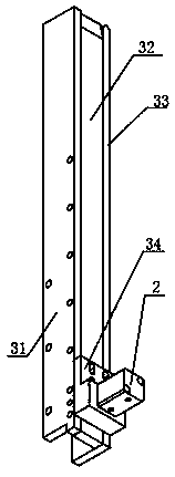
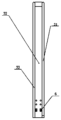
[0033] The flat tube storage unit includes two parallel and vertical lower slides 3. The lower slide is a flat-shaped structure with one side opening surrounded by three panels. The two flat-shaped openings face each other. , Install the cylinder 2 through the cylinder bracket on the back of the shape, and the protruding end of the cylinder 2 passes through the cylinder bracket...


PUM

PropertyMeasurementUnit
lengthaaaaaaaaaa
lengthaaaaaaaaaa

Abstract

The invention discloses a flat tube pushing and limiting device for a threading machine. A hole expander is mounted at the bottom of a lower sliding plate, the end of the hole expander is in a semi-arc or trapezoid, when the hole expander extends forwards under the action of a cylinder, the hole expander opens a flat tube opening parallel to the hole expander, the hole-expanding deformation is 0.4-0.5 mm, and local expansion is conducted, so that the consistency of the tube opening is ensured; in addition, the hole expansion is conducted, meanwhile, the longitudinal pressure of the to-be-threaded flat tube at the lower part of the flat tube is reduced, and it is ensured that the expansion opening is no longer compressed and deformed, so that the threading work is completed; and for ensuring that no wide face contact of a pushing plate and the flat tube exists, pushing blocking blocks are mounted on the two sides of the pushing plate, under the action of the small cylinder, the pushingblocking blocks are lifted or dropped, a pushing mechanism pushes the pushing plate forwards during lifting, the pushing blocking blocks make contact with the bottommost flat tube side wall in a sliding groove, so that the flat tube is pushed out, a standard cylinder is recovered, the pushing blocking blocks are dropped, the flat tube bottom is not damaged, the flat tube side wall is frictionless,and the pollution to the pushing plate is avoided.

Description

technical field [0001] The invention relates to the technical field of belt threading machines, in particular to a flat tube pushing and limiting device for a belt threading machine. Background technique [0002] With the development of society, the automobile industry has also developed accordingly, which makes the automobile supporting industry also present a trend of rapid growth. The assembly requirements of the core as the heat exchange medium are constantly increasing. Therefore, the demand for high-efficiency core assembly equipment is also increasing. [0003] On the one hand, in the work of the modern system, the spoiler belt (fin) of the intercooler of the automobile adopts the flat tube type, and several flat tubes are placed in the lower plate. Due to the action of gravity, the upper flat tube forms pressure on the bottom flat tube, The flat tube at the bottom is deformed, and when the fins are connected to the intercooler tube (that is, the flat tube), because...

Claims


Application Information

Patent Timeline
Patent Type & Authority Applications(China)
IPC IPC(8): B23P19/00B21D41/02
Inventor 郭剑李道营房生贤高波
Owner SHANDONG XINHEYUAN HEAT TRANSFERRING TECH
Why Eureka
Try Eureka