Check patentability & draft patents in minutes with Patsnap Eureka AI!

Myoelectrical complex driving mechanism for foot robot joints

A technology of robot joints and driving mechanisms, applied in motor vehicles, manipulators, program-controlled manipulators, etc., can solve problems such as poor practicability, achieve good practicability, solve uncontrollable compensation torque, and improve control compliance and environmental adaptability. Effect

Active Publication Date: 2019-05-21
NORTHWESTERN POLYTECHNICAL UNIV
View PDF8 Cites 0 Cited by
  • Summary
  • Abstract
  • Description
  • Claims
  • Application Information

AI Technical Summary

Problems solved by technology

[0006] In order to overcome the shortcomings of the poor practicability of the existing foot robot joint drive mechanism, the invention provides an electromuscular compound drive mechanism for the foot robot joint

Method used


Image

  • Myoelectrical complex driving mechanism for foot robot joints
  • Myoelectrical complex driving mechanism for foot robot joints
  • Myoelectrical complex driving mechanism for foot robot joints

Examples


Embodiment Construction

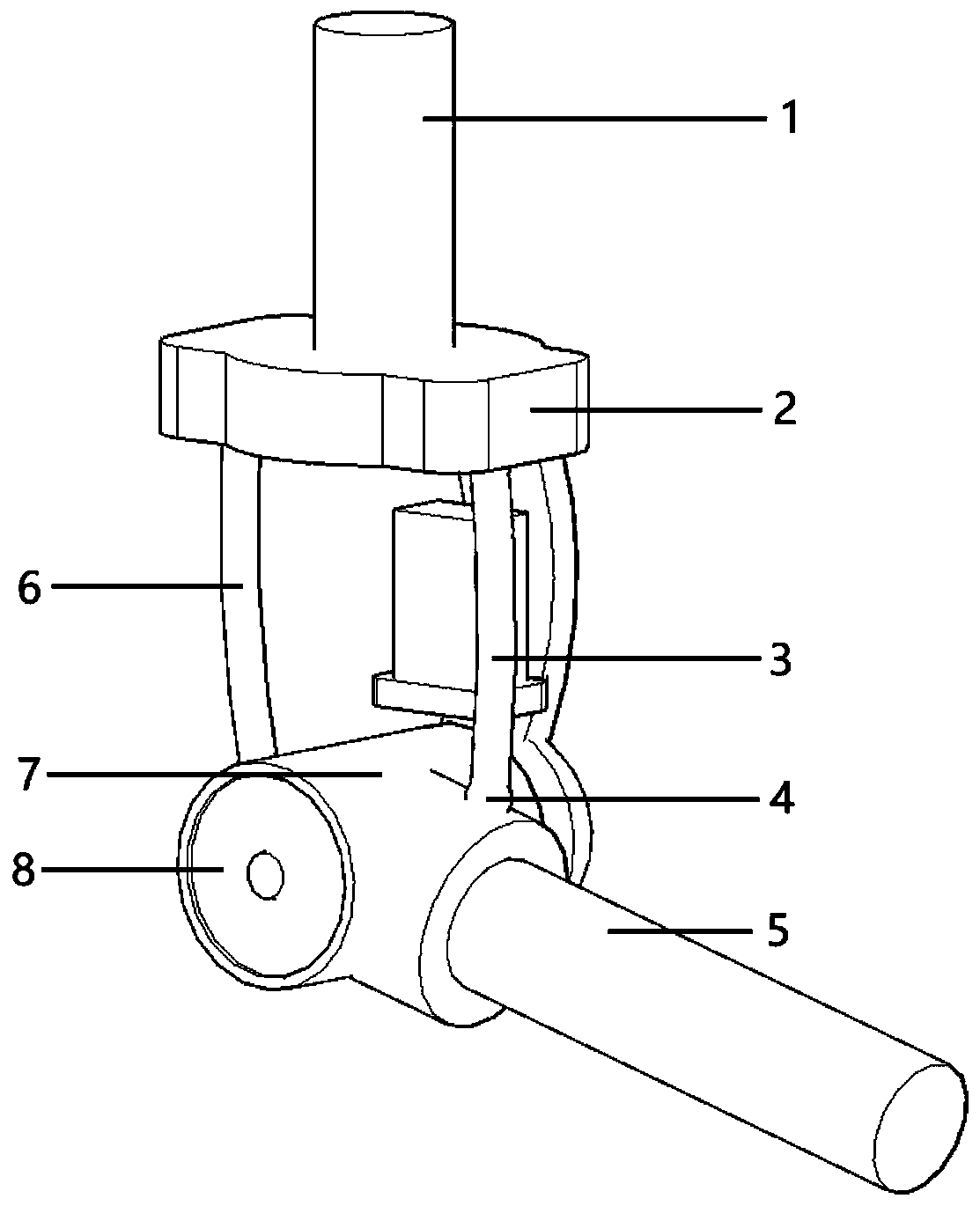
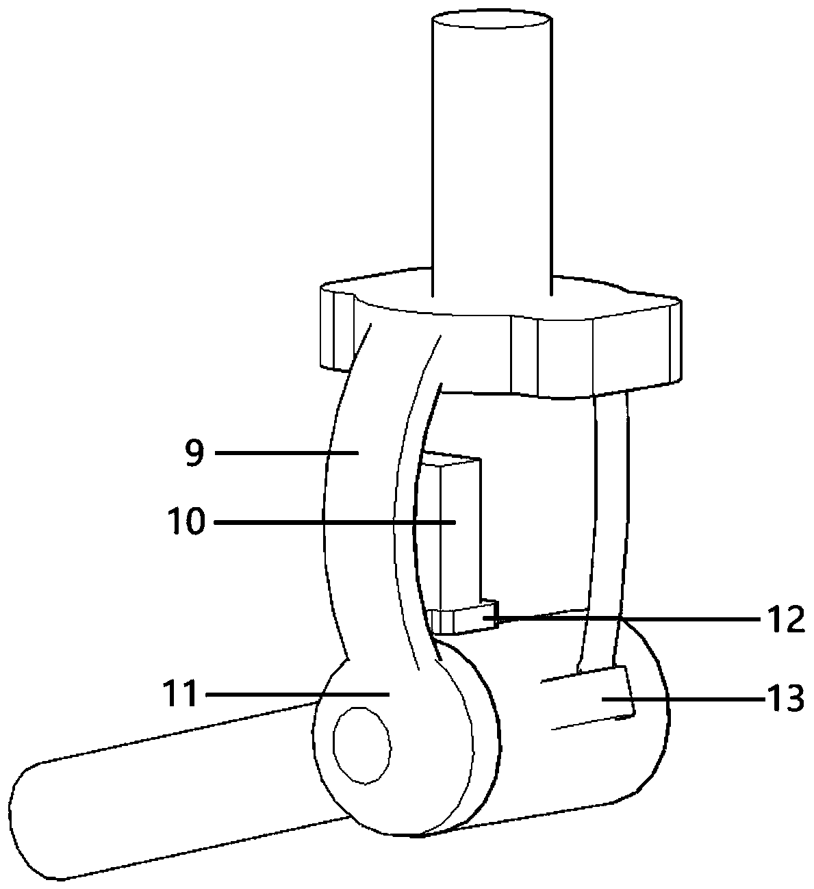
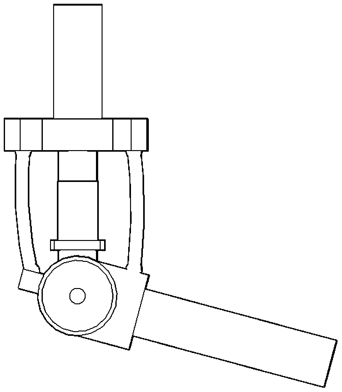
[0024] The following examples refer to Figure 1~6 .

[0025] The electric muscle compound driving mechanism for the joint of the legged robot of the present invention includes an upper bracket 1, a tendon support frame 2, a right tendon 3, a flexible electrode and a fixer 4, a lower bracket 5, a left tendon 6, a connecting shell 7, a motor assembly 8, a connecting Frame 9, controller 10, connecting platform 11 and controller bracket 12.

[0026] The upper part of the upper bracket 1 is a free end connected to other joints, and the lower part of the upper bracket 1 is fixedly connected with the tendon support frame 2 . The tendon support frame 2 plays the role of providing support for the contraction and force application of the tendon. The connecting frame 9 has an arc-shaped structure, providing space for the internal controller 10, and at the same time, the appearance is more similar to the appearance of human muscles. The upper part of the connecting frame 9 is connecte...


PUM


Abstract

The invention discloses a myoelectrical complex driving mechanism for foot robot joints, and solves the technical problem of weak practicability of a traditional foot robot joint driving mechanism. The myoelectrical complex driving mechanism comprises a right tendon, a lower bracket, a left tendon, a connecting shell, a motor module and a controller. In the process of the complex driving mechanismmoving from a downward inclined state of the lower bracket to a horizontal state, the controller sends control signals to the motor module to rotate a motor anticlockwise, and meanwhile, controls terminal voltage of the left tendon and the right tendon as needed to elongate the left tendon and shrink the right tendon to provide anticlockwise torque to the connecting shell and the motor module soas to drive anticlockwise rotation of the lower bracket. Similarly, in the process of the complex driving mechanism moving from the horizontal state of the lower bracket to the downward inclined state, the motor is rotated clockwise, the left tendon is shrunk, and the right tendon is elongated, so that the clockwise torque is provided to the connecting shell and the motor module, and the lower bracket is rotated to rotate clockwise to achieve high practicability.

Description

technical field [0001] The invention relates to a joint driving mechanism of a legged robot, in particular to an electro-muscle compound driving mechanism for a joint of a legged robot. Background technique [0002] The movement characteristics of the footed robot in discontinuous contact with the ground enable it to adapt to complex terrain such as mountains, so it has a larger range of motion than the wheeled or tracked mobile robot, and the joint is one of the core components of the footed robot. The bionic action characteristics of the footed robot require its joint drive to have the characteristics of fast response speed, high torque density, and light weight. The motor drive is widely used in robot joint drive due to its precise control and fast response. [0003] Robot joints are affected by gravity (gravitational moment) due to their own weight, and the load increases. Most robot joints use powerful, heavy motors and reducers to provide sufficient torque for robot ...

Claims


Application Information

Patent Timeline
IPC IPC(8): B25J9/12B25J17/02B62D57/032
Inventor 汪远林窦满峰王婷秦浩然张晨
Owner NORTHWESTERN POLYTECHNICAL UNIV
Features
  • R&D
  • Intellectual Property
  • Life Sciences
  • Materials
  • Tech Scout
  • Unparalleled Data Quality
  • Higher Quality Content
  • 60% Fewer Hallucinations
Learn More