A device and method for detecting the location of ice blockage in natural gas pipelines

A technology for natural gas and pipelines, which is applied in the field of devices for detecting the position of ice blockage in natural gas pipelines, can solve problems such as ice blockage in natural gas pipelines, and achieve low cost, convenient operation, and the effect of solving ice blockage problems

Active Publication Date: 2020-03-17
XI AN JIAOTONG UNIV
View PDF26 Cites 0 Cited by
  • Summary
  • Abstract
  • Description
  • Claims
  • Application Information

AI Technical Summary

Problems solved by technology

[0010] The object of the present invention is to provide a device and method for detecting the ice blockage position of natural gas pipelines, so as to solve the positioning problem of ice blockage positions of natural gas pipelines. Provide new technical measures for ice blockage problem

Method used


Image

  • A device and method for detecting the location of ice blockage in natural gas pipelines
  • A device and method for detecting the location of ice blockage in natural gas pipelines
  • A device and method for detecting the location of ice blockage in natural gas pipelines

Examples


Embodiment 1

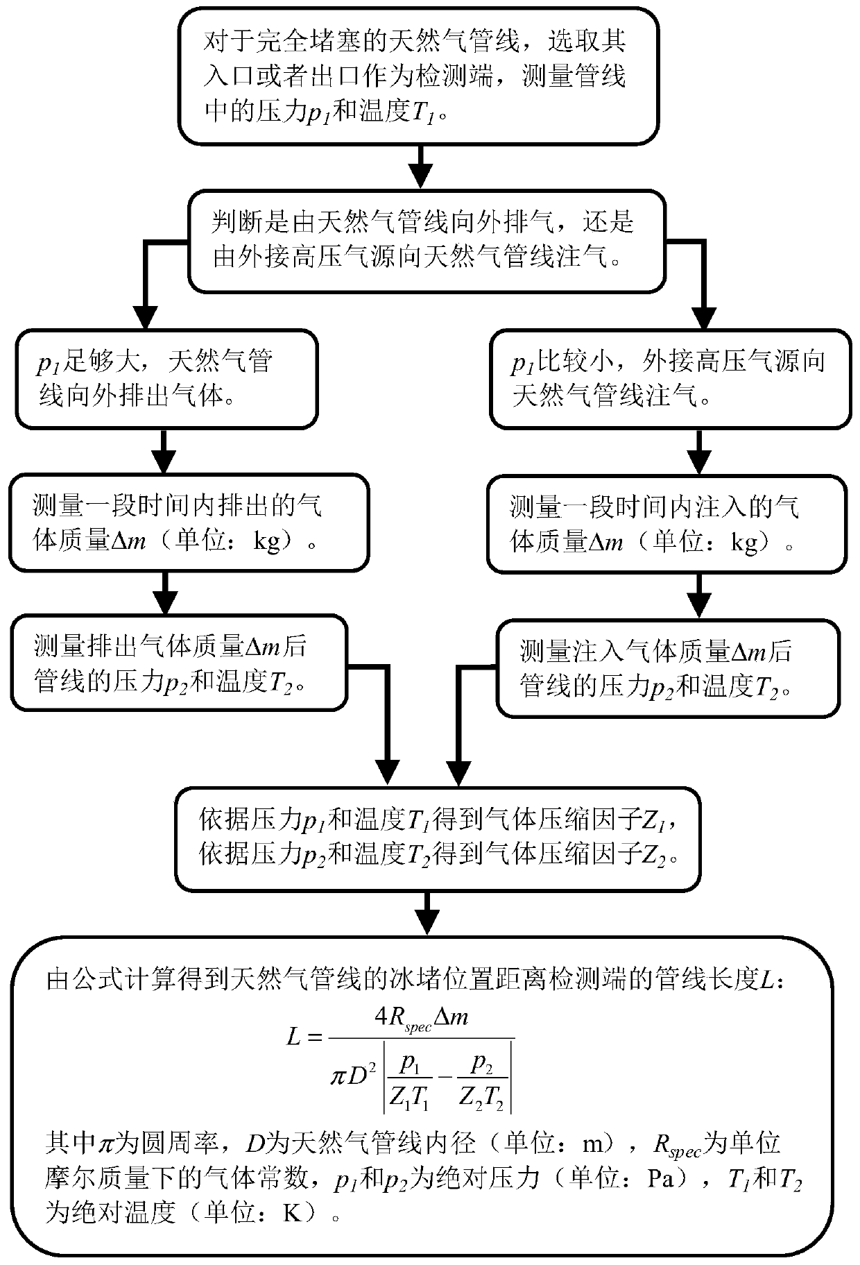
[0054] A natural gas pipeline completely blocked due to ice formation inside the pipeline, the pressure in the pipeline p 1 It is known that it is relatively large, and the detection of the position of ice blockage adopts the scheme of exhausting from the inside of the pipeline to the outside. At this time, the specific implementation method is as follows:

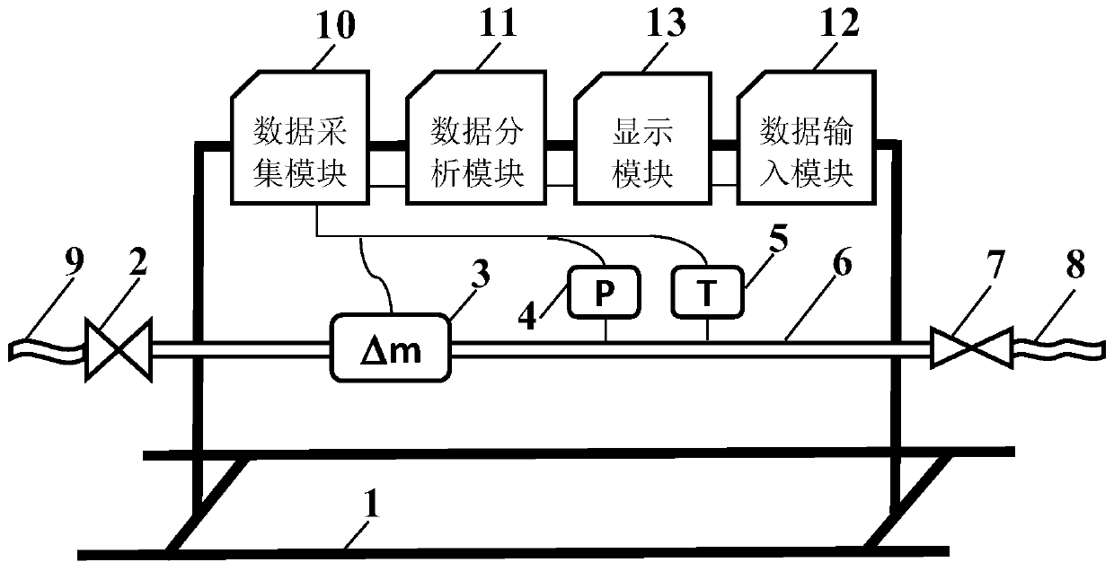
[0055] 1) For a completely blocked natural gas pipeline, select its inlet or outlet as the detection end, connect the high-pressure side adapter pipe 8 of the detection device to the natural gas pipeline, and connect the low-pressure side adapter pipe 9 to the atmosphere.

[0056] 2) Open the communication valve 7, make the measuring pipe 6 communicate with the natural gas pipeline, use the pressure sensor 4 and the temperature sensor 5 to measure the pressure p of the natural gas pipeline 1 and T 1 , and at the same time the data acquisition module 10 converts p 1 and T 1 transmitted to the data analysis module 11 and ...

Embodiment 2

[0065] A natural gas pipeline completely blocked due to ice formation inside the pipeline, the pressure in the pipeline p 1 It is known that it is relatively small, and the position of ice blockage is detected by injecting gas into the pipeline from a high-pressure gas source. At this time, the specific implementation method is as follows:

[0066] 1) For a completely blocked natural gas pipeline, select its inlet or outlet as the detection end, connect the high-pressure side adapter pipe 8 of the detection device to the high-pressure gas source, and connect the low-pressure side adapter pipe 9 to the natural gas pipeline at the detection end.

[0067] 2) Keep the communication valve 7 in the closed state, open the flow regulating valve 2, connect the measuring pipe 6 with the natural gas pipeline, and use the pressure sensor 4 and the temperature sensor 5 to measure the pressure p of the natural gas pipeline 1 and T 1 , and at the same time the data acquisition module 10 con...

Embodiment 3

[0076] A natural gas pipeline completely blocked due to ice formation inside the pipeline, the pressure in the pipeline p 1 Unknown, the specific implementation method of detecting the location of ice blockage at this time is as follows:

[0077] 1) For a completely blocked natural gas pipeline, select its inlet or outlet as the detection end, and connect the high-pressure side transfer pipe 8 of the detection device to the natural gas pipeline at the detection end.

[0078] 2) Open the communication valve 7, make the measuring pipe 6 communicate with the natural gas pipeline, use the pressure sensor 4 and the temperature sensor 5 to measure the pressure p of the natural gas pipeline 1 and T 1 , and at the same time the data sampling module 10 converts p 1 and T 1 transmitted to the data analysis module 11 and the display module 13.

[0079] 3) Determine whether the ice-blocked natural gas pipeline is exhausted or the external high-pressure gas source is used to inject gas...


PUM


Abstract

The invention discloses a device and method for detecting the ice blockage position of a natural gas pipeline. An operating maintenance person can rapidly determine the specific position of the blockage point, completely blocked due to icing, of the natural gas pipeline. The detecting device comprises a flow adjusting valve, a gas mass flowmeter, a pressure sensor, a temperature sensor, a measuring pipe, a communication valve, a high-pressure side adapter pipe and a low-pressure side adapter pipe which are arranged on a wholly mounted support, detection data of the gas mass flowmeter, the pressure sensor and the temperature sensor are collected by a data collection module and transmitted to a data analysis module, in combination with parameters of the physical property, and the pipeline inner diameter input by a data input module, calculation is carried out, the ice blockage position is obtained, and the detection result is displayed in a display module. The detection method comprisesthe steps that through measuring of parameters of gas mass accumulatively discharged out of or injected into the natural gas pipeline and pressure, temperature, pipeline inner diameter and the like ofthe pipeline, the pipeline length between the ice blockage point and the detection position can be calculated, and the ice blockage position of the natural gas pipeline can be determined.

Description

technical field [0001] The invention relates to the field of natural gas transmission pipelines, in particular to a device and method for detecting ice blockage positions of natural gas pipelines. Background technique [0002] Natural gas fields in Northwest my country will encounter ice blockage of natural gas production pipelines in winter. The freezing period here usually lasts for 4-5 months, the average temperature in winter is around -20°C, and the average thickness of the ground permafrost is 1.2-1.5 meters , The production pipelines of natural gas fields have been in the subzero field environment for a long time. Since the natural gas produced by natural gas wells will contain a small amount of water or water vapor, when the ground temperature is below zero for a long time in winter, some natural gas gathering and transportation pipelines in the field will be completely blocked due to the freezing of a small amount of water in the pipe, or due to low temperature The ...

Claims


Application Information

Patent Timeline
Patent Type & Authority Patents(China)
IPC IPC(8): F17D5/00
Inventor 刘磊王江南高玉堂李子阳周芳德
Owner XI AN JIAOTONG UNIV
Why Eureka
Try Eureka