Plate-fin type heat exchanger baffle spray-head structure sealing head

A plate-fin heat exchanger and head technology, which is applied to direct contact heat exchangers, heat exchanger types, heat exchanger shells, etc. Pressure drop increases and other problems, to achieve the effect of easy production and processing, reducing gas flow resistance, and reducing energy consumption

Inactive Publication Date: 2019-05-21
ZHEJIANG UNIV OF TECH
View PDF8 Cites 7 Cited by
  • Summary
  • Abstract
  • Description
  • Claims
  • Application Information

AI Technical Summary

Problems solved by technology

[0003] Chinese utility model patent 200420042241.4 discloses a head structure of a uniform deflector fin heat exchanger. By adding a perforated baffle with different apertures inside the original head, the flow rate to each outlet of the head is controlled. , so that the flow into the channels of each layer inside the heat exchanger is as equal as possible, thereby improving the heat exchange efficiency, but because the baffle is installed parallel to the outlet surface, the fluid flow resistance becomes larger, and the energy loss increases, which has certain disadvantages
[0004] Chinese utility model patent 201720416089.9 discloses a plate-fin heat exchanger head that can evenly distribute two-phase fluid. According to the pyramid principle, a multi-layer deflector is arranged inside the head, and the inflowing fluid passes through the primary deflector. Divide into two streams and flow to the second-level guide plate, and then divide into four streams, eight streams, sixteen streams... and flow out from each outlet. Although this structure can achieve a uniform distribution effect to a certain extent, after multi-stage diversion, The pressure drop of the fluid increases, the energy consumption increases, the maximum effect cannot be exerted, and its structure is not easy to produce and process

Method used


Image

  • Plate-fin type heat exchanger baffle spray-head structure sealing head
  • Plate-fin type heat exchanger baffle spray-head structure sealing head
  • Plate-fin type heat exchanger baffle spray-head structure sealing head

Examples


Embodiment Construction

[0025] The present invention will be further described below in conjunction with accompanying drawing of description, but protection scope of the present invention is not limited thereto:

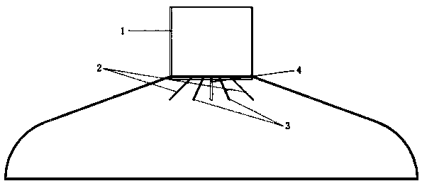
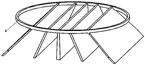
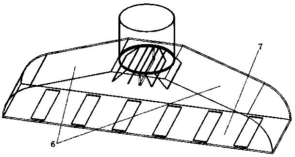
[0026] see Figure 1-3 , a plate-fin heat exchanger baffle nozzle structure head, including the head header 1, the baffle consisting of two baffles I2, two baffles II3, one baffle III4 and a welded ring 5 The nozzle structure, as well as the inclined square shell 6 and the outlet surface 7, the baffle I2, the baffle II3 and the baffle III4 in the baffle nozzle structure are connected with the ring 5 by welding, and then the ring 5 is connected to the main pipe of the head 1 end for solder connection.

[0027] The baffle I2 is arranged on both sides of the baffle III4, and the baffle II3 is arranged at a position between the baffle I2 and the baffle III4.

[0028] Among them, the angle range between the baffle I2 and the horizontal line is 40°-50°, the angle range between the baffle II3 an...


PUM


Abstract

The invention discloses a plate-fin type heat exchanger baffle spray-head structure sealing head. The plate-fin type heat exchanger baffle spray-head structure sealing head comprises a sealing head main pipe, a shell disposed at the bottom of the sealing head main pipe and an outlet surface arranged at the bottom of the shell. A circular ring is welded to the bottom of the sealing head main pipe,a baffle spray-head structure is arranged on the circular ring, the baffle spray-head structure includes baffles I, baffles II and a baffle III, the baffles I are arranged on both sides of the baffleIII, and the baffles II are arranged at the positions between the baffles I and the baffle III. The plate-fin type heat exchanger baffle spray-head structure sealing head has the beneficial effects that inflowing high-pressure gas can be injected to corresponding outlet regions by additionally arranging the baffle spray-head structure at the tail end of the main pipe, and the uniformity of flow distribution at each outlet is effectively improved.

Description

technical field [0001] The invention relates to the technical field of multi-channel heat exchanger head structure, in particular to a head with a baffle nozzle structure for a plate-fin heat exchanger. Background technique [0002] Due to its compact structure, light weight, high heat transfer efficiency, and strong adaptability, plate-fin heat exchangers are widely used in many fields such as air separation equipment, petrochemical, transportation equipment, and aerospace. Among them, in the air separation equipment, the plate-fin heat exchanger is the key equipment for heat exchange such as condensation, liquefaction, and evaporation. The heat exchange efficiency directly determines the energy consumption in the air separation process, which has an important impact on economic benefits. influences. Uneven inlet flow distribution is a common problem of low heat exchange efficiency of plate-fin heat exchangers. This problem can be greatly improved by innovating and improvi...

Claims


Application Information

Patent Timeline
Patent Type & Authority Applications(China)
IPC IPC(8): F28F25/12F28F9/22F28F9/18
CPCF28F9/0268
Inventor 彭翔李登洪姜少飞高启龙李吉泉
Owner ZHEJIANG UNIV OF TECH
Why Eureka
Try Eureka