
Ground fault point positioning method and device for rail transit traction auxiliary converter

A technology for auxiliary converters and ground faults, which is applied in the field of rail transit, can solve problems such as complex internal structures, equipment loss, and heavy workload, and achieve the goals of improving operational safety and reliability, avoiding serious damage, and improving maintenance efficiency Effect

Pending Publication Date: 2019-05-21
CHINA ACADEMY OF RAILWAY SCI CORP LTD +2
View PDF4 Cites 7 Cited by
  • Summary
  • Abstract
  • Description
  • Claims
  • Application Information

AI Technical Summary

Problems solved by technology

[0004] However, due to the complex internal structure of the traction auxiliary converter and the large number of components, even after the ground fault of the traction auxiliary converter is known, a lot of tedious and time-consuming manual investigations are required to find out the fault. , during this period, due to the time-consuming process of the investigation process, it is easy to cause serious damage to the equipment in a short period of time, which will not only cause equipment loss, but even affect the normal operation of rail transit vehicles, and cannot meet the needs of modern railways for intelligent and security requirements
That is to say, the existing ground fault location method of the traction auxiliary converter needs to manually find the fault location after the fault is determined, which makes the fault location time-consuming, heavy workload and easy damage to the faulty equipment.

Method used


Image

  • Ground fault point positioning method and device for rail transit traction auxiliary converter
  • Ground fault point positioning method and device for rail transit traction auxiliary converter
  • Ground fault point positioning method and device for rail transit traction auxiliary converter

Examples


Embodiment Construction

[0070] In order to make the purpose, technical solutions and advantages of the embodiments of the present application clearer, the technical solutions in the embodiments of the present application will be clearly and completely described below in conjunction with the drawings in the embodiments of the present application. Obviously, the described embodiments It is a part of the embodiments of this application, not all of them. Based on the embodiments in this application, all other embodiments obtained by persons of ordinary skill in the art without creative efforts fall within the protection scope of this application.

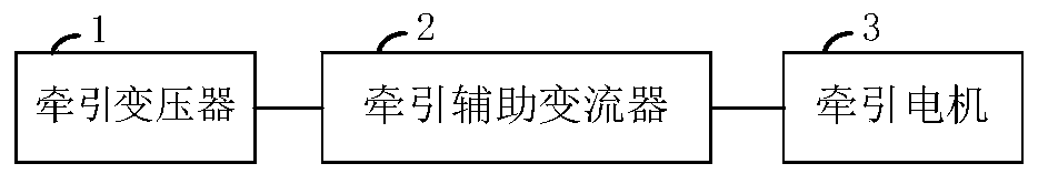
[0071] Considering that the traditional ground detection method of traction auxiliary converter does not have the function of automatically locating the ground fault point, and because the internal structure of the converter is complex and there are many components, manual troubleshooting is cumbersome; For transformers, if the ground fault cannot be quickly l...


PUM


Abstract

The invention provides a ground fault point positioning method and device for a rail transit traction auxiliary converter. The method comprises the following steps: after the connection between an inversion side and a grounding detection circuit is disconnected, judging whether a grounding fault occurs at the inversion side or a traction motor connected to the inversion side according to the comparison result of a target voltage ratio of a traction auxiliary converter determined to have the grounding fault and a first preset range; if not, according to comparison results between the target voltage ratio and a second preset range and between the target voltage ratio and a third preset range respectively, and judging whether the grounding fault occurs at a negative electrode or the positiveelectrode of the direct current link of a rectification side, and if the grounding fault does not occur at the negative electrode or the positive electrode of the direct current link of the rectification side and the grounding voltage has an alternating current component, positioning the grounding fault at the secondary side of a traction transformer between the traction transformer and the rectification side. According to the method, the ground fault of the traction auxiliary converter can be automatically and quickly positioned, and the positioning process is high in accuracy.

Description

technical field [0001] The present application relates to the technical field of rail transit, in particular to a method and device for locating a ground fault point of a traction auxiliary converter of rail transit. Background technique [0002] The ground detection of power electronic equipment is an important technology, which involves the safety of equipment and personnel. At present, traction auxiliary converters of locomotives or EMUs in rail transit vehicles are usually installed between the traction transformer and the traction motor of the locomotive or EMU, and the ground detection circuit is arranged between the rectification side of the traction auxiliary converter and the traction motor. Between the inverter side, it is usually composed of two voltage divider resistors connected in series between the positive and negative busbars of the DC link on the rectifier side, and filter capacitors connected to both ends of the negative busbar resistance. Among them, the ...

Claims


Application Information

Patent Timeline
IPC IPC(8): G01R31/08G01R19/165
CPCB60L9/24B60L50/51B60L2200/26B60L3/0069B60L2210/20Y02T10/70Y02T10/72
Inventor 刘洋高吉磊赵震张义海卜丽东刘伟志左鹏殷振环谢冰若刘佳璐
Owner CHINA ACADEMY OF RAILWAY SCI CORP LTD
Learn More