Energy storage device

A device and energy storage technology, applied in the directions of hybrid capacitor terminals, hybrid boxes/casings/packages, etc., can solve the problems of increasing parts processing costs and testing costs, high processing accuracy requirements, and difficult processing, saving assembly time. , Improve production efficiency and save time

Pending Publication Date: 2019-05-21
JINAN SHENGQUAN GROUP SHARE HLDG
View PDF0 Cites 0 Cited by
  • Summary
  • Abstract
  • Description
  • Claims
  • Application Information

AI Technical Summary

Problems solved by technology

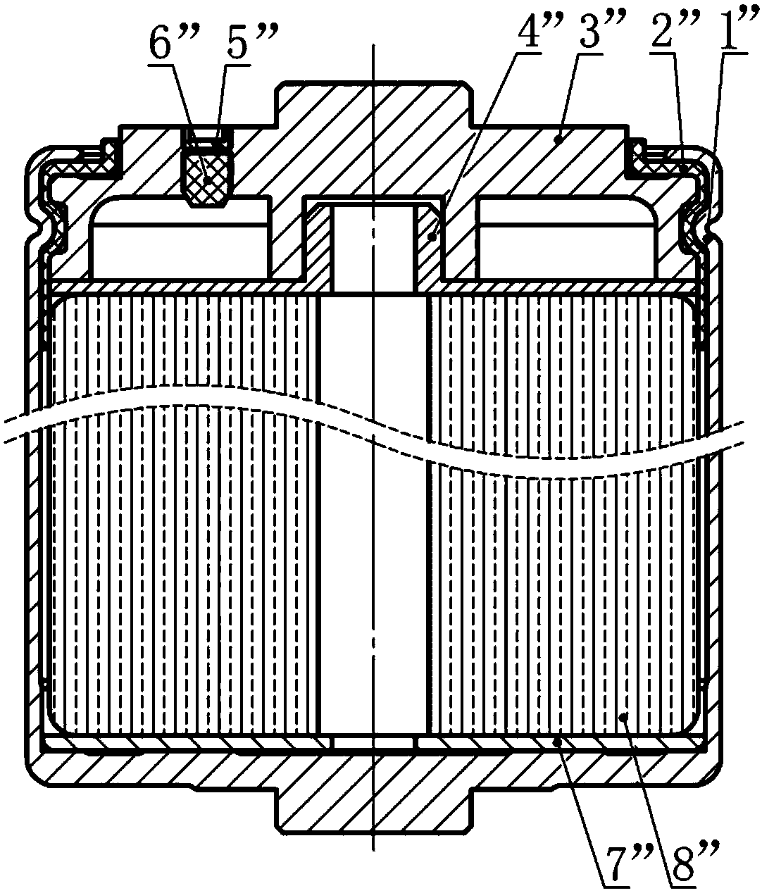
[0007] The positive lead-out method of the energy storage device of this structure and the shell designed with one end opening are basically the same as the energy storage device of the first structural form, and the problems caused by it are the same as above; the negative lead-out method adopts transition fit and welding. This structure requires high machining accuracy for the joint between the current collector 4” and the negative electrode cover 3”, and the processing is difficult, which also increases the processing cost and testing cost of the parts

Method used


Image

  • Energy storage device
  • Energy storage device
  • Energy storage device

Examples


Embodiment Construction

[0034] In order to make the technical problems, technical solutions and advantages to be solved by the present invention clearer, the following will describe in detail with reference to the drawings and specific embodiments.

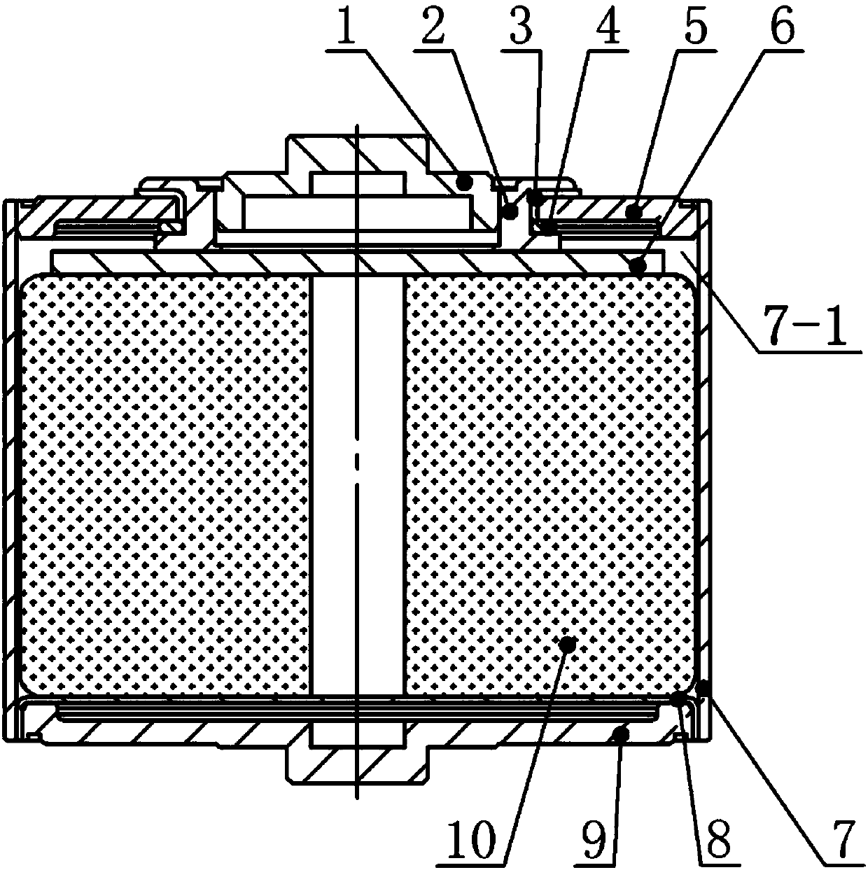
[0035] The present invention provides an energy device, such as Figure 3 to Figure 7 As shown, it includes a casing 7, a positive electrode lead-out structure, a core 10, a negative electrode cover 5 and a negative electrode lead-out structure, wherein:

[0036] The end of the casing 7 is provided with a first through hole 7-1, and the positive electrode lead-out structure, the core body 10 and the negative electrode cover 5 are sequentially sleeved in the first through hole 7-1 from the lower end of the casing 7;

[0037] The positive electrode lead-out structure includes a current collector 8 connected to the core 10 and a positive lead-out cover 9. The end of the current collector 8 is provided with a blind hole 8-1. In a through hole 7-1, the lead-ou...


PUM


Abstract

The invention discloses an energy storage device. The end of a shell of the energy storage device is provided with a first through hole, and a positive electrode lead-out structure, a core body and anegative electrode cover are sequentially arranged in the first through hole in clearance and sleeved manners from the lower end of the shell; the positive electrode lead-out structure includes a current collecting piece and a lead-out cover as a positive electrode, the outer edge of the current collecting piece is inserted in the first through hole in a clearance fit manner, the lead-out cover isinserted into a blind hole of the current collecting piece in a clearance fit manner, and the end of the current collecting piece, the end of the lead-out cover and the end of the shell are connectedin a once welding manner; and a negative electrode lead-out structure comprises a current collector, a pole as a negative pole and an adapter column arranged between the current collector and the pole, the adapter column is provided with a third through hole being in clearance fit with the pole, the current collector is connected to the lower end of the adapter column in a welded manner, and theadapter column and the pole are welded and connection at the upper end of the third through hole. The energy storage device can ensure the reliability, the stability and the service life, the production efficiency can be improved, and the processing cost can be reduced.

Description

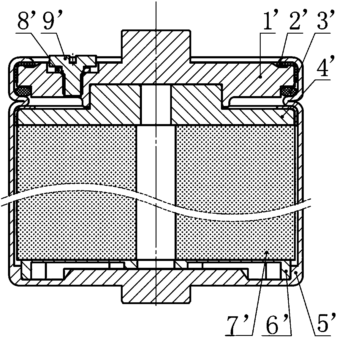
technical field [0001] The invention relates to the technical field of energy storage devices. Background technique [0002] Batteries or supercapacitors are widely used as energy storage devices in industry, energy, military and other fields. Among them, the packaging structure of the supercapacitor mainly plays a role in preventing the leakage of the electrolyte and preventing the influence of water, dust and other external harsh environments on the supercapacitor itself; at the same time, the supercapacitor also provides a power lead-out pole for Connections with external devices. As a key part of the supercapacitor, the packaging structure used not only has an important impact on the resistance of the supercapacitor, but also is crucial to the stability, reliability and life of the monomer. [0003] At present, the packaging structure commonly used in energy storage devices has the following two forms. The first structure form is as follows: figure 1 As shown, a core ...

Claims


Application Information

Patent Timeline
Patent Type & Authority Applications(China)
IPC IPC(8): H01G11/74H01G11/82
CPCY02E60/13
Inventor 祝建勋
Owner JINAN SHENGQUAN GROUP SHARE HLDG
Why Eureka
Try Eureka