Conductive slip ring dissimilar material pressure poured piece numerical control turning method

A technology of dissimilar materials and pressure casting, applied in the manufacturing of slip rings, etc., can solve the problems of groove flanging, difficult to guarantee product quality, relying on operator experience and skills, etc., to eliminate space distortion, ensure the quality of the machined surface, and restrain deformation. Effect

Inactive Publication Date: 2019-05-21
SHANGHAI AEROSPACE EQUIP MFG GENERAL FACTORY
View PDF6 Cites 0 Cited by
  • Summary
  • Abstract
  • Description
  • Claims
  • Application Information

AI Technical Summary

Problems solved by technology

However, due to the objective limitations of the pressure casting process, after each part is cast, there are relative position differences and spatial distortions between the metal conductive ring and the resin insulating ring in the axial direction, and the above differences and distortions are uncertain. This means that there is a lack of benchmarks for turning metal conductive rings
[0004] The existing process is to use manual visual inspection to find the center position of the metal conductive ring, and manually set the tool to turn two V-shaped grooves in sequence, which relies heavily on the operator's experience and skills, and the position accuracy of the two V-shaped grooves is difficult to guarantee.
In addition, since the adjacent two sides of each metal conductive ring are resin insulating rings, turning the double V-shaped grooves in turn will easily cause the grooves to flang, and the product quality is difficult to guarantee

Method used


Image

  • Conductive slip ring dissimilar material pressure poured piece numerical control turning method
  • Conductive slip ring dissimilar material pressure poured piece numerical control turning method
  • Conductive slip ring dissimilar material pressure poured piece numerical control turning method

Examples


Embodiment Construction

[0027] Hereinafter, the present invention will be further described in conjunction with the drawings and embodiments.

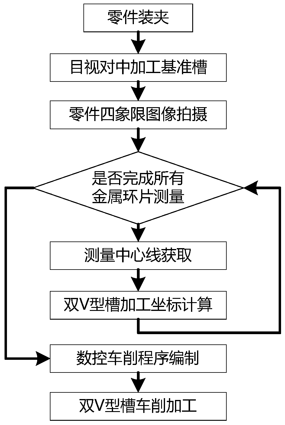
[0028] refer to figure 2 According to the embodiments of the present invention, the CNC turning process of the conductive slip ring dissimilar material pressure casting includes the following steps.

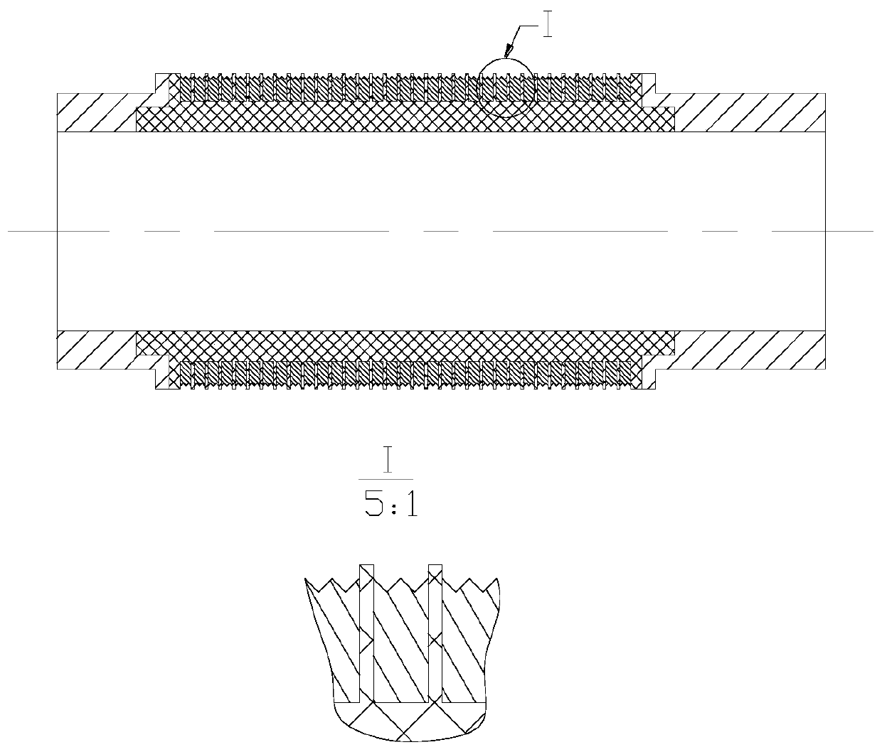
[0029] Step 1. Clamp the part with the chuck of the CNC lathe, and process a reference groove with the ring groove turning tool based on visual inspection at the center of the first metal ring, and record the Z-axis coordinates of the CNC lathe CNC system at this moment.

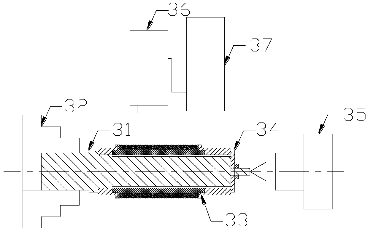
[0030] refer to image 3 , the part clamping method described in the embodiment of the present invention is that one end of the mandrel 31 is first clamped on the CNC lathe chuck 32, the mandrel 31 and the inner hole of the part 33 are fitted with a small gap, and then the end cover 34 is connected to the mandrel 31 The other end is threaded to position the part axially, and the radial forc...


PUM


Abstract

The invention provides a conductive slip ring dissimilar material pressure poured piece numerical control turning method. The method comprises the steps that first, a benchmark slot is machined in a part fixture and a numerical control lathe chuck through an annular slot turning tool; second, a camera-shooting measuring system is used to perform shooting on four quadrants of a part; third, in thecamera-shooting measuring system, an image, obtained in the second step, of the four quadrants of the part is processed; fourth, a mid-value of a positive extreme value and a negative extreme value isused as a measuring center line of a first metal ring sheet; fifth, a benchmark slot center line on the first metal ring sheet is read, and the distance between the benchmark slot center line and a measuring center line is calculated; sixth, as to other metal ring sheets of the part, the fourth step is repeated to acquire the measuring center line of each metal ring sheet, and then the fifth stepis repeated to calculate the distance between the benchmark slot center line and the measuring center line of each metal ring sheet; and seventh, a numerical control turning program is made accordingto obtained Z-axis coordinates of a numerical control system during turning of a double-V-shaped slot of each metal ring sheet, and a forming turning tool of the double-V-shaped slots is adopted to perform turning.

Description

technical field [0001] The invention relates to the field of numerical control turning processing, in particular to a numerical control turning processing method of a conductive slip ring dissimilar material pressure casting. Background technique [0002] Conductive slip ring is a precision electromechanical device that transmits current and signal between two relative rotating mechanisms. It is suitable for occasions that require unlimited continuous or intermittent rotation and transmits power or signals from rotating parts to fixed parts. As a key component of current and signal transmission, conductive slip rings are widely used in space vehicles and satellites, such as solar cell wing-to-sun orientation mechanisms, gyro mechanisms, etc. As a space motion mechanism that requires long-term on-orbit operation, the conductive slip ring is one of the few single-point failure devices in the spacecraft system, and its reliability and life are very important. [0003] The non-...

Claims


Application Information

Patent Timeline
Patent Type & Authority Applications(China)
IPC IPC(8): H01R43/10
Inventor 刘晓周金强代海聪逄格波朱磊
Owner SHANGHAI AEROSPACE EQUIP MFG GENERAL FACTORY
Why Eureka
Try Eureka