Self-positioning clamping lathe

A self-positioning and lathe technology, applied in the direction of positioning devices, clamping, turning equipment, etc., can solve the problems of large machining errors, low precision, and difficulty in ensuring the coaxiality of the workpiece and the rotating spindle, and achieve convenient feeding and transportation. The effect of improving production and processing efficiency

Inactive Publication Date: 2019-05-24
ZHEJIANG FUSHI MACHINERY TECH
View PDF1 Cites 6 Cited by
  • Summary
  • Abstract
  • Description
  • Claims
  • Application Information

AI Technical Summary

Problems solved by technology

[0006] The present invention provides a self-positioning and clamping lathe for the deficiencies of the prior art. While moving to the clamping and rotating device through the automatic feeding device, the workpieces falling from the automatic feeding device are transported to the clamping and rotating device at intervals After contacting with the clamping and rotating device, the self-centering component realizes the centering of the workpiece and the clamping and rotating device, and realizes the automatic clamping of the workpiece by the clamping component while the automatic feeding device continues to move forward. At the same time, cooperate with the cutting control component to control the distance between the cutting component and the workpiece, realize the integration of automatic feeding, positioning, clamping and processing of the workpiece, and solve the problem in the prior art that it is difficult to ensure the synchronization between the workpiece and the rotating spindle when clamping. Axial degree, large machining error during machining, and low precision technical problems

Method used


Image

  • Self-positioning clamping lathe
  • Self-positioning clamping lathe
  • Self-positioning clamping lathe

Examples


Embodiment 1

[0070] Embodiments of the present invention are described in detail below, examples of which are shown in the drawings, wherein the same or similar reference numerals designate the same or similar elements or elements having the same or similar functions throughout. The embodiments described below by referring to the figures are exemplary and are intended to explain the present invention and should not be construed as limiting the present invention.

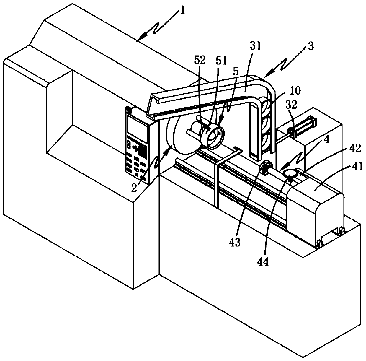
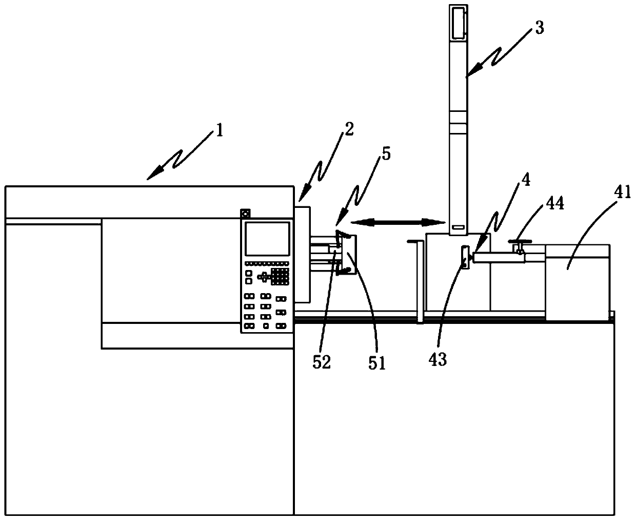
[0071] Such as figure 1 , 2 As shown in and 3, a self-positioning and clamping lathe includes a lathe body 1, a rotating main shaft 2 that is rotatably arranged on the lathe body 1, and an automatic feeding device 3 that is arranged on one side of the lathe body 1, and include:

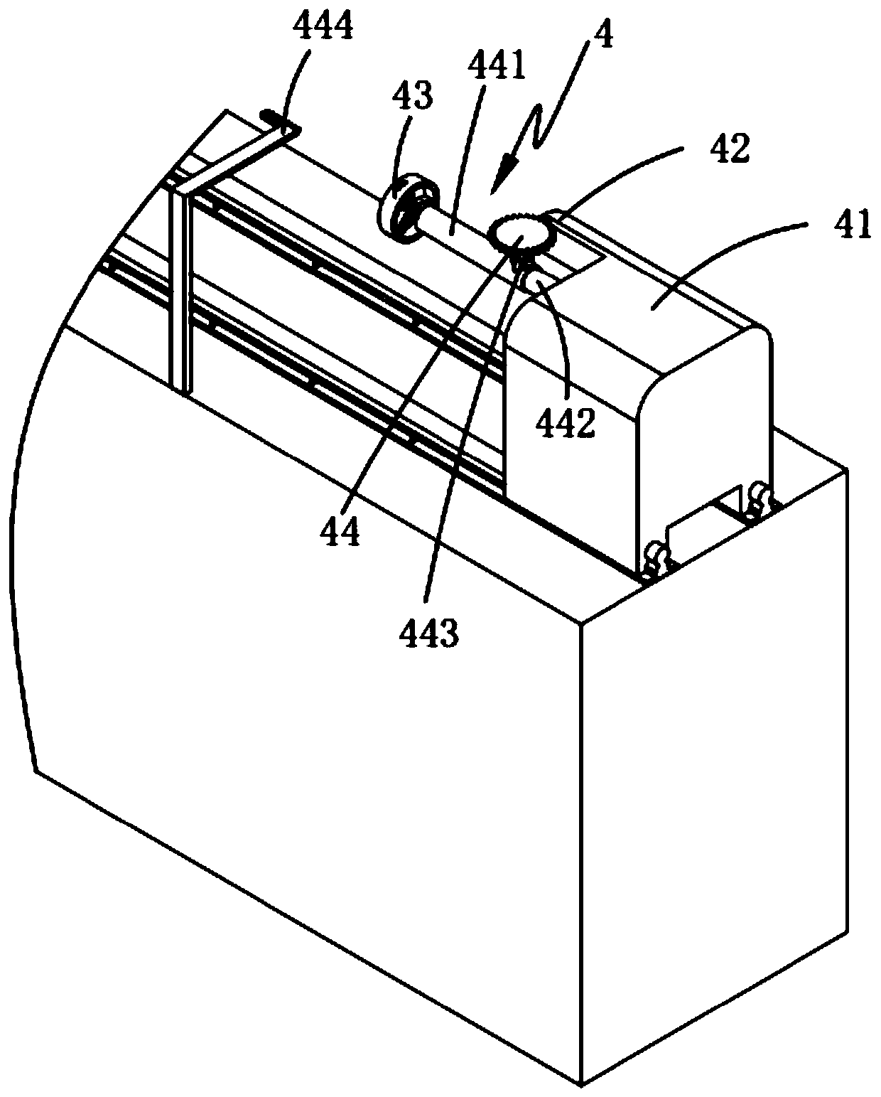
[0072] Automatic feeding device 4, described automatic feeding device 4 is slidably arranged on the lathe body 1 and this automatic feeding device 4 is positioned at the side on the axial direction of described rotating main shaft 2, and this automatic...


PUM


Abstract

The invention provides a self-positioning clamping lathe. The self-positioning clamping lathe comprises a lathe body, a rotating spindle, an automatic supplementing device, an automatic feeding deviceand a clamp rotating device; the automatic feeding device comprises a feeding driving assembly, a cutting assembly, a self-centering assembly and a cutting control assembly; the clamp rotating devicecomprises a clamping assembly and a clamping control assembly; when the automatic feeding device moves towards the rotating spindle, workpieces falling from the automatic supplementing device at intervals are transported into the clamp rotating device, make contact with the clamp rotating device and then are self-centered, in the process that the automatic feeding device continues moving forwards, the workpieces are automatically clamped through the clamping assembly, meanwhile, the distance between the cutting assembly and the workpieces is controlled through the cutting control assembly, thus automatic feeding, positioning, clamping and machining integration of workpieces are achieved, and the technical problems that in the prior art, the coaxiality between the workpieces and the rotating spindle is difficultly ensured during clamping, the machining error is large during machining, and the precision is low are solved.

Description

technical field [0001] The invention relates to the field of metal surface treatment, in particular to a self-positioning and clamping lathe. Background technique [0002] There are many ways to polish the metal surface, among which the three methods of mechanical polishing, chemical polishing, and electrochemical polishing occupy a large market share in industrial production. [0003] For the mechanical polishing method, the current equipment investment is expensive and the operation is complicated, so it is difficult to widely promote and use it in the small-profit polishing industry. Complicated surface polishing is mainly manual polishing, using mechanical polishing wheels and belt polishing methods, relying on the proficiency of workers and visually controlling the polishing quality, the stability is low, and at the same time the polishing environment where most workers are located is very harsh. The dust and vibration generated have a great impact on the body and the ...

Claims


Application Information

Patent Timeline
IPC IPC(8): B23B3/06B23Q7/00B23Q3/12B23Q3/18
CPCB23B3/06B23Q3/12B23Q3/18B23Q7/00
Inventor 傅利忠
Owner ZHEJIANG FUSHI MACHINERY TECH
Why Eureka
Try Eureka