Die with telescopic handle mechanism

A mold and post-mold technology, applied in the field of molds with shrinking mechanism, can solve the problems of small application range, inability to apply telescopic molds, and inability to reduce the size of telescopic molds, and achieve high purity, uniformity, and excellent metallurgical quality , to meet the effect of normal production demand

Pending Publication Date: 2019-05-24
WUXI MODA TECH
View PDF1 Cites 0 Cited by
  • Summary
  • Abstract
  • Description
  • Claims
  • Application Information

AI Technical Summary

Problems solved by technology

However, this kind of telescopic switch is to move the first insert and the second insert through a mechanical structure to realize the telescopic function, so the size of the retractable switch cannot be made smaller, and the retractable switch cannot be applied to very small products, and the application range is small. The problem

Method used


Image

  • Die with telescopic handle mechanism
  • Die with telescopic handle mechanism
  • Die with telescopic handle mechanism

Examples


Embodiment

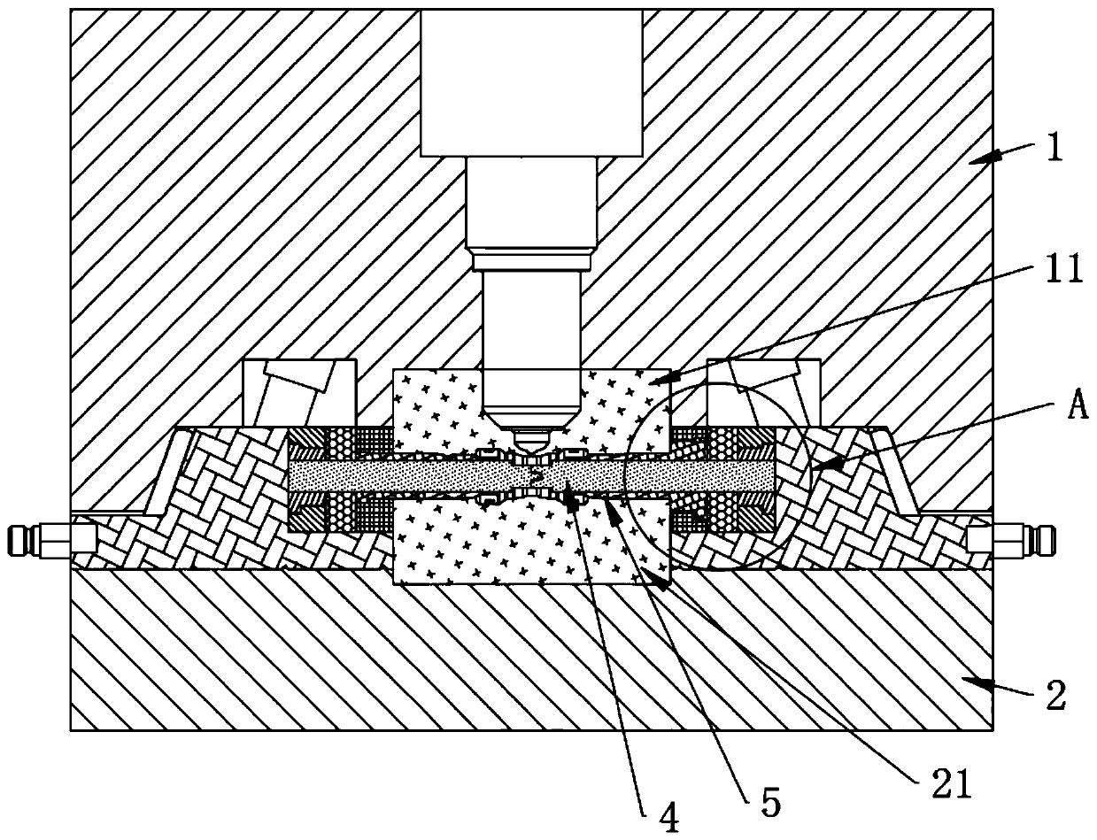
[0039] Embodiment: a kind of mold of band shrinkage mechanism, as figure 1 As shown, it includes a front mold 1 and a rear mold 2, the front mold 1 is provided with an upper cavity plate 11, the rear mold 2 is provided with a lower cavity plate 21, and the upper cavity plate 11 and the lower cavity plate 21 are closed to form a product The cavity of the external shape.

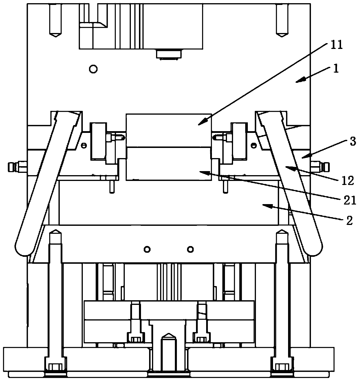
[0040] like figure 2 As shown, shrink parts are arranged between the front mold 1 and the rear mold 2, the shrink parts include the slider seat 3, the rear mold 2 is provided with a chute for the slider seat 3 to fit and slide, and the front mold 1 is set There is an inclined guide post 12 passing through the slider seat 3. When the front mold 1 moves relative to the rear mold 2, the slider seat 3 will slide under the promotion of the inclined guide post 12.

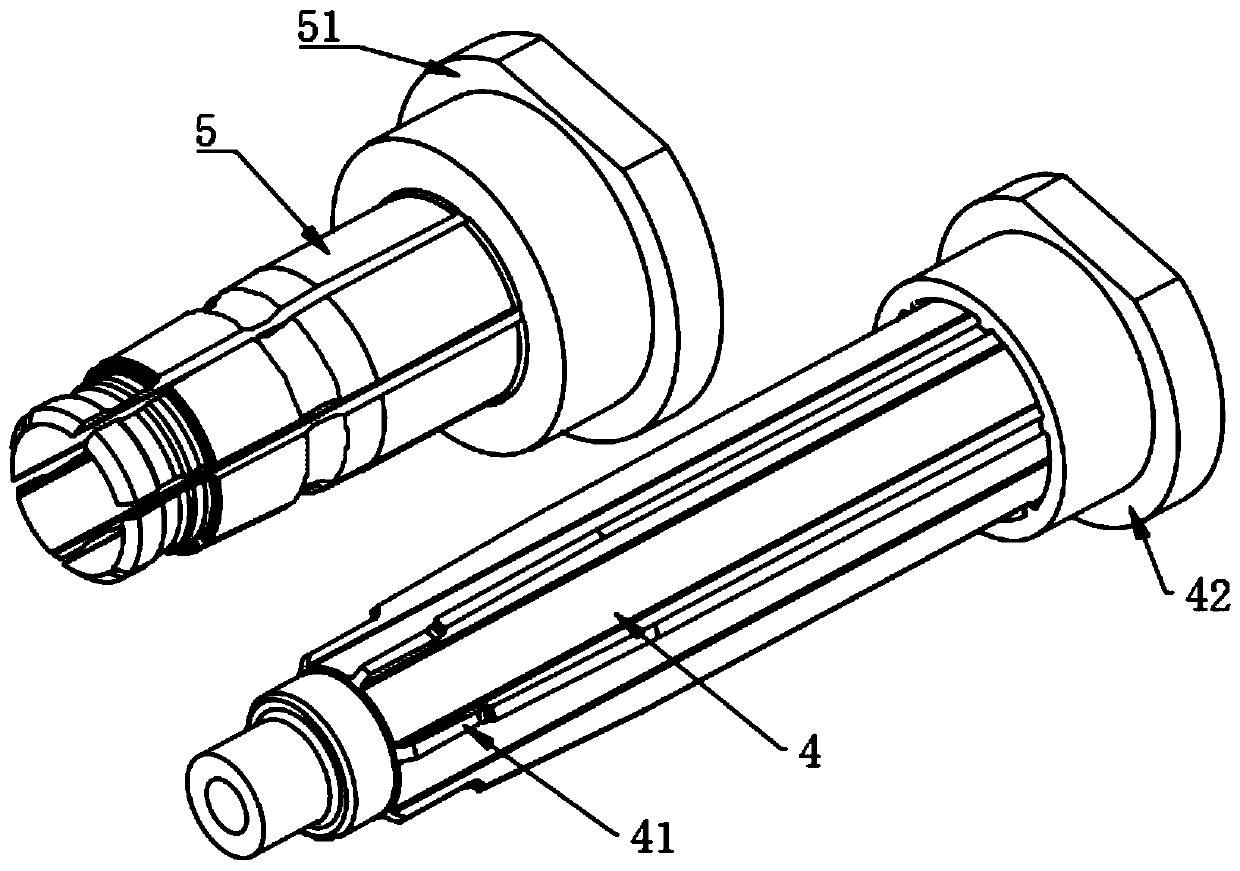
[0041] like figure 1 As shown, the shrinkage part is provided with a slider insert 4 inserted into the cavity and a plurality of undercut inserts 5 ...


PUM


Abstract

The invention relates to a die which has an effect of being wide in application range and discloses a die with a telescopic handle mechanism. The die comprises a front die body and a rear die body. Atelescopic handle part is arranged between the front die body and the rear die body and comprises a sliding block base. The front die body is provided with an oblique guide column penetrating throughthe sliding block base. The telescopic handle part is provided with a sliding block embedding pin inserted into a cavity, and multiple inverted buckling inserts forming a circle in an enclosure manner. The center line of the sliding block embedding pin and the center line of the inverted buckling inserts coincide. The sliding block embedding pin and the inverted buckling inserts are folded to formthe shape of an inner cavity of a product. The sliding block embedding pin is fixedly connected with a sliding block base. Each inverted buckling insert is made of a metal material capable of deforming elastically. When the oblique guide column is away from the rear die body along with the front die body, the sliding block base is away from the cavity under pushing of the oblique guide column. After a gap is generated between the sliding block embedding pin and the inverted buckling inserts, the inverted buckling inserts will move along with the sliding block base. By means of cooperation ofthe inverted buckling inserts capable of deforming elastically and the sliding block embedding pin, the application range of the telescopic handle part is enlarged.

Description

technical field [0001] The present invention relates to a mold, more specifically, it relates to a mold with shrinking mechanism. Background technique [0002] Mold is a variety of molds and tools used in industrial production for injection molding, blow molding, extrusion, die-casting or forging forming, smelting, stamping and other methods to obtain the required products. Under the action of external force, the blank becomes a specific shape and size. pieces of tools. [0003] The patent of notification number CN206217090U and publication date 20170606 discloses a telescopic core, including an inner insert and an outer insert sleeved on the inner insert, the top of the inner insert is closed and the bottom end is open, and the inner insert There is a hollow channel inside, and the hollow channel communicates with the cooling water through the opening; the inner insert is in the shape of a cone from the bottom to the top, and an inner chute and an inner slider are arranged...

Claims


Application Information

Patent Timeline
Patent Type & Authority Applications(China)
IPC IPC(8): B29C45/33B29C45/44B29C45/26
Inventor 张征虞晓峰
Owner WUXI MODA TECH
Why Eureka
Try Eureka