Temperature control system and temperature control method for multiple QCMs (quartz crystal microbalances)

A temperature control system and constant temperature technology, which is applied in the direction of using electric mode for temperature control, etc., can solve the problems of complicated pipeline installation and large consumption of liquid nitrogen, and achieve simple installation process, low consumption of liquid nitrogen, and the number of pipelines. less effect

Active Publication Date: 2019-05-24
BEIHANG UNIV
View PDF10 Cites 1 Cited by
  • Summary
  • Abstract
  • Description
  • Claims
  • Application Information

AI Technical Summary

Problems solved by technology

[0005] The purpose of the present invention is to provide a temperature control system for multiple QCMs, to solve the technical problems in the prior ar

Method used


Image

  • Temperature control system and temperature control method for multiple QCMs (quartz crystal microbalances)
  • Temperature control system and temperature control method for multiple QCMs (quartz crystal microbalances)
  • Temperature control system and temperature control method for multiple QCMs (quartz crystal microbalances)

Examples


Embodiment 1

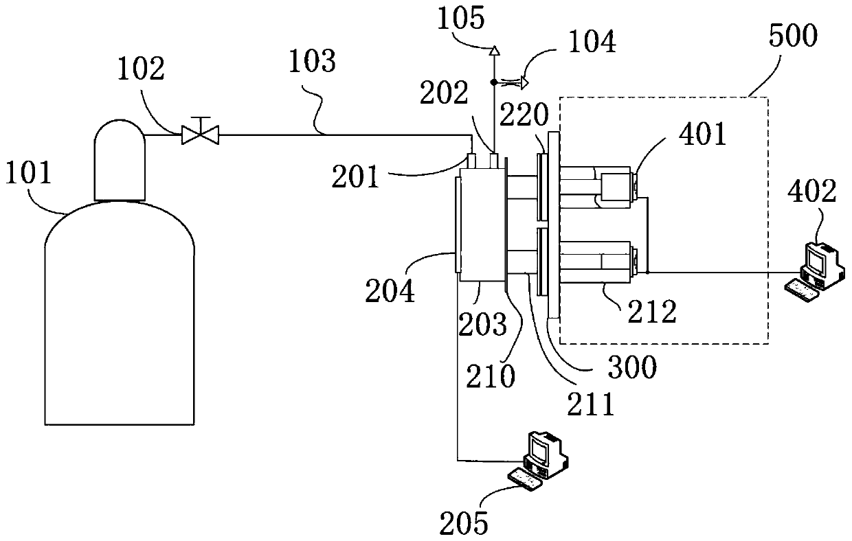
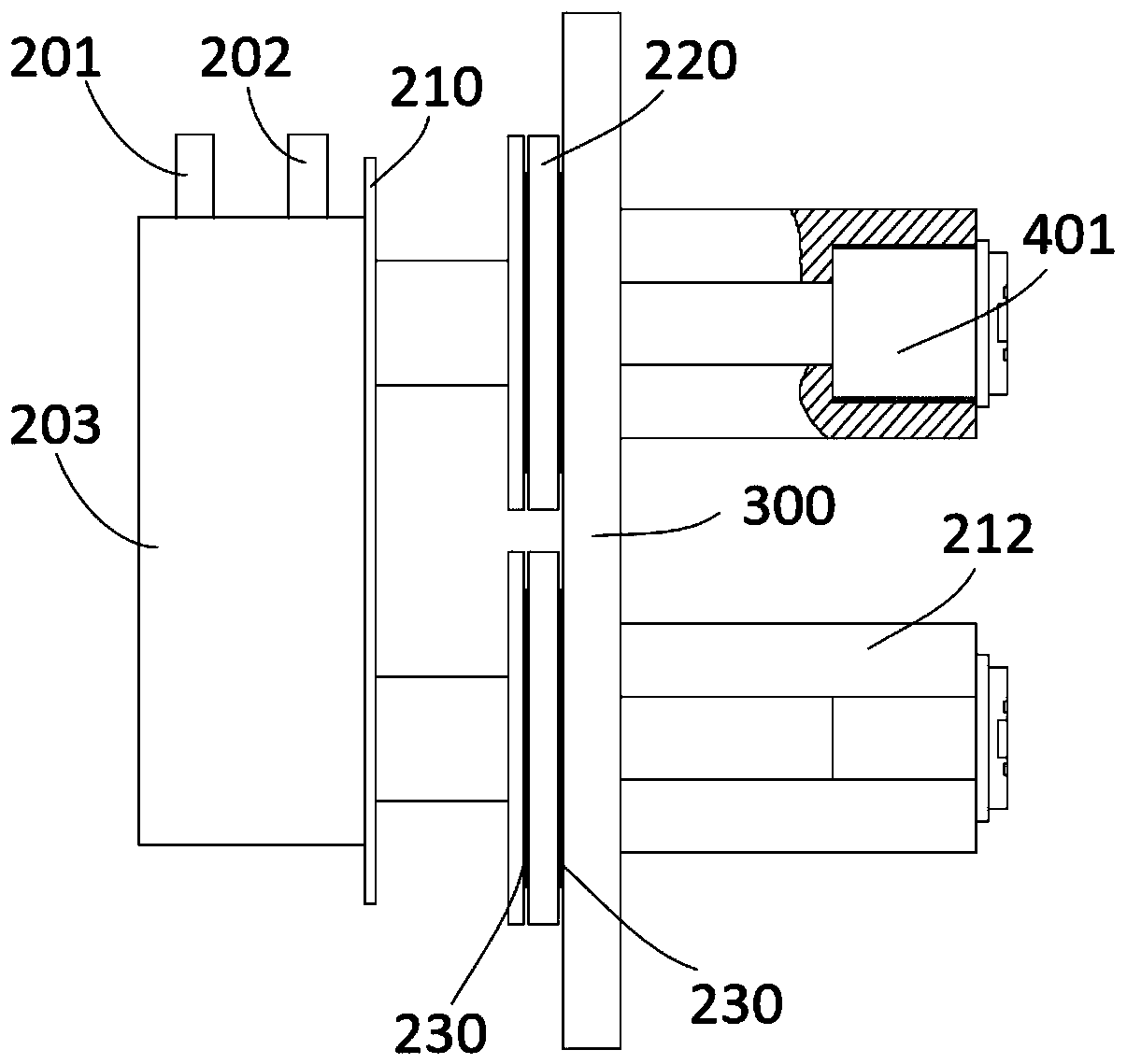
[0049] Such as figure 1 As shown, the temperature control system for multiple QCMs provided by the embodiment of the present invention includes: a constant temperature mechanism, a heat transfer assembly, and a plurality of quartz crystal microbalances (for ease of description, the quartz crystal microbalances are hereinafter referred to as QCMs) , its reference number in the accompanying drawings is 401). in:

[0050] The constant temperature mechanism includes: a thermostat 203, a refrigerator and a heater, and the refrigerator and the heater are connected with the thermostat 203 respectively. The liquid nitrogen tank 101 transports liquid nitrogen from the pressurized liquid nitrogen tank 101 to the thermostat 203, specifically, the liquid nitrogen enters the circulation pipeline inside the thermostat 203 through the liquid nitrogen inlet 201 of the thermostat 203, so that the thermostat The temperature of 203 is lowered, and finally discharged into the atmosphere through...

Embodiment 2

[0069] Embodiment 2 of the present invention proposes a temperature control method, which is applied to the temperature control system for multiple QCMs provided in Embodiment 1 above (such as figure 1 shown), temperature control methods include:

[0070] Multiple quartz crystal microbalances are installed on the heat transfer assembly of the temperature control system for multiple QCMs, and the lowest value T among the target temperatures of multiple quartz crystal microbalances is taken min ;

[0071] Regulate the temperature of thermostat 203 by refrigerator and heater, make the temperature of thermostat 203 reach T min ;

[0072] The heat transfer assembly conducts the temperature of the thermostat 203 to the quartz crystal microbalance, so that the temperature of each quartz crystal microbalance reaches T min ;

[0073] The corresponding QCM401 is heated by the heating element on the surface of the QCM401, so that the temperature of each QCM401 rises to its respective...


PUM


Abstract

The invention provides a temperature control system and a temperature control method for multiple QCMs (quartz crystal microbalances), relates to the technical field of temperature control and aims tosolve the problem that a cooling system used for testing the QCMs at the same time is high in liquid nitrogen consumption and complex in pipeline mounting. The temperature control system comprises aconstant temperature mechanism, a heat transfer component and the quartz crystal microbalances, the constant temperature mechanism comprises a thermostat, a refrigerator and a heater, the refrigeratorcomprises a self-pressurizing liquid nitrogen tank communicated with the thermostat, the heat transfer component comprises a connecting member and multiple clamping members, the connecting member isconnected with the thermostat and the clamping members, the quartz crystal microbalances are mounted to the clamping members, and a heating member is mounted on each quartz crystal microbalance. In the constant temperature mechanism of the temperature control system, a self-pressurizing liquid nitrogen tank can lower temperature of all QCMs by only delivering liquid nitrogen to the constant temperature, so that the temperature control system is low in liquid nitrogen consumption, few in pipeline number and simpler in mounting process.

Description

technical field [0001] The invention relates to the technical field of temperature control, in particular to a temperature control system and a temperature control method for multiple QCMs. Background technique [0002] When conducting research on the deposition characteristics of bicomponent engine plume pollutants in a space environment, it is necessary to set up a tooling to hold a QCM (Quartz crystal microbalance) to measure the mass change of the material to be tested after gas adsorption and desorption At the same time, cryogenic control of the QCM surface under vacuum conditions is required to simulate the low-temperature conditions on the surface of spacecraft materials in space. [0003] The QCM is fixed in the vacuum chamber through the clamp, and the clamp is connected to the cooling system, which is used to lower the QCM for low temperature control. The cooling system usually includes a cold storage module, which is installed inside the vacuum chamber and connec...

Claims


Application Information

Patent Timeline
IPC IPC(8): G05D23/19
Inventor 蔡国飙吴成赓苏杨贺碧蛟翁惠焱
Owner BEIHANG UNIV
Why Eureka
Try Eureka