Thin film assembly for photovoltaic solar cell lamination

A technology of solar cells and thin-film modules, applied in the field of solar cells, can solve problems such as inability to fix solar cells and poor stability, and achieve the effects of not being loose, improving stability, and ensuring normal operation

Pending Publication Date: 2019-05-24
ANKANG UNIV
View PDF7 Cites 0 Cited by
  • Summary
  • Abstract
  • Description
  • Claims
  • Application Information

AI Technical Summary

Problems solved by technology

Existing thin film modules for photovoltaic solar cell lamination cannot effectively fix solar cells and have poor stability

Method used


Image

  • Thin film assembly for photovoltaic solar cell lamination
  • Thin film assembly for photovoltaic solar cell lamination
  • Thin film assembly for photovoltaic solar cell lamination

Examples


Embodiment 1

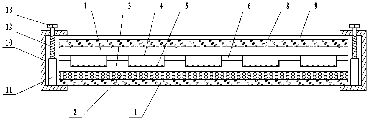
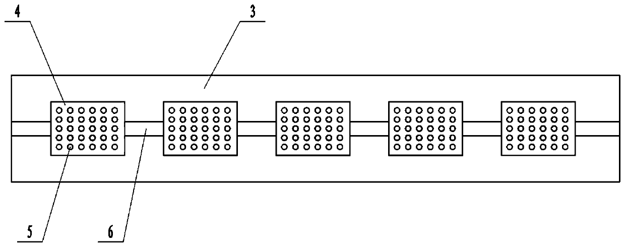
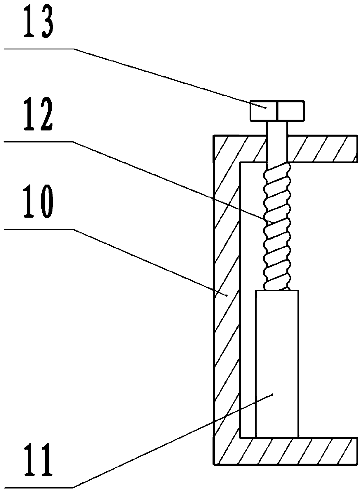
[0021] see Figure 1-3 , in an embodiment of the present invention, a thin film assembly for photovoltaic solar cell lamination, comprising a lower glass layer 1, a lower PVB thin film layer 3, a mounting groove 4 and an upper PVB thin film layer 7, the upper surface of the lower glass layer 1 A buffer layer 2 is laid, and the material of the buffer layer 2 is silica gel, and the buffer layer 2 is used to play a buffering role. The upper surface of the buffer layer 2 is laid with a lower PVB film layer 3, and the upper surface of the lower PVB film layer 3 is processed with installation recesses. Groove 4, bus bar installation groove 6, the solar cell is placed in the installation groove 4, and the bottom of the installation groove 4 is processed with anti-slip protrusions 5, which play a role in anti-skid, so that the solar cell remains stable, and the bus bar is installed in the In the bus bar installation groove 6, the bottom of the bus bar installation groove 6 is processe...

Embodiment 2

[0024] A thin film assembly for photovoltaic solar cell lamination, comprising a lower glass layer 1, a lower PVB thin film layer 3, an installation groove 4 and an upper PVB thin film layer 7, the upper surface of the lower glass layer 1 is laid with a buffer layer 2, the buffer layer The material of layer 2 is silica gel, and the buffer layer 2 is used for buffering. The upper surface of the buffer layer 2 is laid with a lower PVB film layer 3, and the upper surface of the lower PVB film layer 3 is processed with installation grooves 4 and bus bar installation grooves. 6. The solar cell is placed in the installation groove 4, and the bottom of the installation groove 4 is processed with anti-slip protrusions 5, which play an anti-skid role and keep the solar cell stable. The bus bar is installed in the bus bar installation groove 6, The bottom of the bus bar installation groove 6 is processed into an arc shape, which is convenient for installation. The upper surface of the lo...


PUM


Abstract

The invention relates to the technical field of solar cells. More specifically, the invention relates to a thin film assembly for photovoltaic solar cell lamination. The thin film assembly comprises alower glass layer, a lower PVB film layer, an installation groove and an upper PVB film layer. A buffer layer is laid on the upper surface of the lower glass layer. The lower PVB film layer is laid on the upper surface of the buffer layer. The installation groove and a bus bar installation groove are formed in the upper surface of the lower PVB film layer. A solar cell piece is placed in the installation groove. A bus bar is mounted in the bus bar installation groove. The upper PVB film layer is laid on the upper surface of the lower PVB film layer. An upper glass layer is laid above the upper PVB film layer. According to the invention, the thin film assembly is convenient to assemble and install. After the packaging is completed, the solar cell piece is not prone to loosening. The fog isprevented from being formed on the upper surface of the upper glass layer by brushing the anti-fog coating. The lower glass layer and the upper glass layer are clamped through a U-shaped clamp, and the stability is further improved. The problem that a solar cell piece in an existing thin film module cannot be effectively fixed is solved.

Description

technical field [0001] The invention relates to the technical field of solar cells, more specifically, a thin film assembly for lamination of photovoltaic solar cells. Background technique [0002] A solar cell is a device that directly converts light energy into electrical energy through the photoelectric effect or photochemical effect. Solar photovoltaic cells (photovoltaic cells for short) are used to directly convert the sun's light energy into electrical energy. At present, silicon solar cells based on silicon are widely used in terrestrial photovoltaic systems, which can be divided into monocrystalline silicon, polycrystalline silicon, and amorphous silicon solar cells. In terms of comprehensive performance such as energy conversion efficiency and service life, monocrystalline silicon and polycrystalline silicon cells are superior to amorphous silicon cells. Polysilicon is less efficient than monocrystalline silicon, but it is cheaper. [0003] Photovoltaic solar ce...

Claims


Application Information

Patent Timeline
IPC IPC(8): H01L31/048
CPCY02E10/50
Inventor 贾晓菲
Owner ANKANG UNIV
Why Eureka
Try Eureka