A high-efficiency photovoltaic cable stripping machine

A photovoltaic cable and wire stripping machine technology, which is applied in the direction of dismantling/armoured cable equipment, etc., can solve the problems of difficult to adjust and position the stripping accurately, inconvenient control and operation, and reduce the efficiency of stripping, so as to improve the stripping efficiency. Efficiency and quality, realizing stripping automation, and improving the effect of stripping quality

Active Publication Date: 2020-05-29
吴江市华林精密五金机械有限公司
View PDF7 Cites 0 Cited by
  • Summary
  • Abstract
  • Description
  • Claims
  • Application Information

AI Technical Summary

Problems solved by technology

[0002] Solar technology will become one of the green energy technologies in the future. Solar energy or photovoltaic (PV) is widely used in China. Photovoltaic cable is a kind of electron beam cross-link cable. In practical applications, it is often necessary to strip the insulating rubber of the outer layer of the cable. It can be used normally, but the existing photovoltaic cable stripping machine is not easy to control and operate, and has a low degree of automation. Hidden dangers reduce the stripping efficiency. During the cutting process, the wires are easily damaged, and the applicability to cables of different sizes is poor, which reduces the quality of the stripping. Therefore, how to design a high-efficiency photovoltaic cable stripping machine has become our current problem to be solved

Method used


Image

  • A high-efficiency photovoltaic cable stripping machine
  • A high-efficiency photovoltaic cable stripping machine
  • A high-efficiency photovoltaic cable stripping machine

Examples


Embodiment

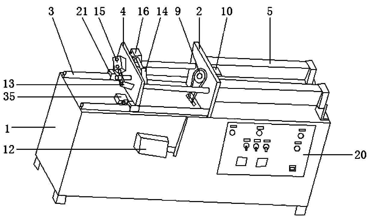
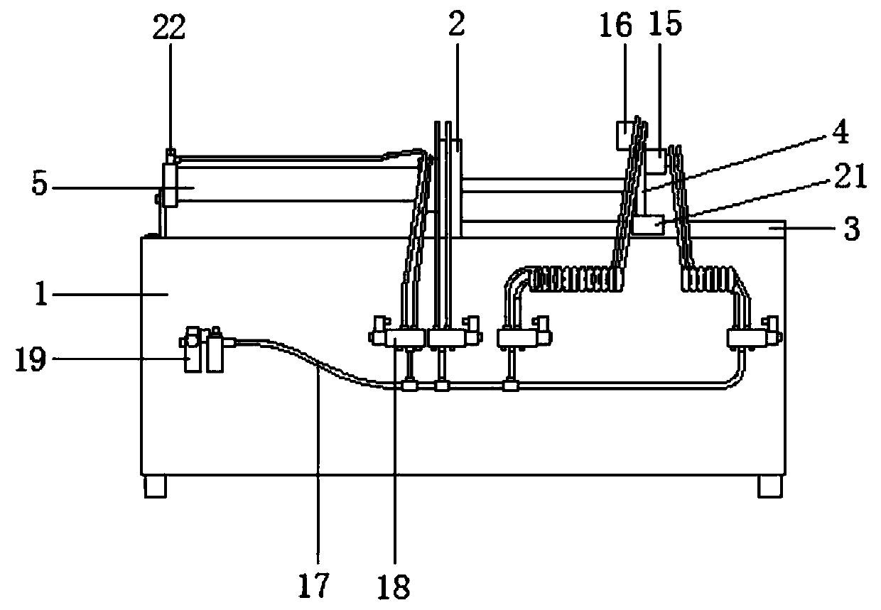
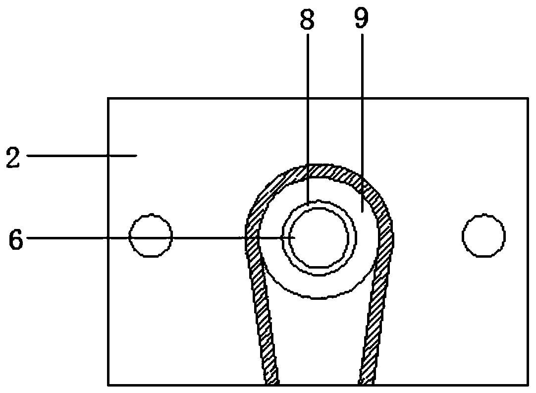
[0027] see Figure 1-Figure 7 As shown, the present invention provides a technical solution: a high-efficiency photovoltaic cable stripping machine, including a chassis 1, a fixed plate 2 is vertically connected to the center of the top of the chassis 1, and a rail 3 is symmetrically connected to the left side of the top of the chassis 1 , the top of the rail 3 is slidably connected with a movable plate 4 to facilitate the movement of the movable plate 4, and the right side of the top of the cabinet 1 is symmetrically connected with a stripping cylinder 5, and the piston rod of the stripping cylinder 5 slides through the fixed plate 2 The rear is fixedly connected to the side of the movable plate 4 to provide the power for stripping. The center of the fixed plate 2 and the movable plate 4 are respectively provided with a first stripping hole 6 and a second stripping hole 7. The first stripping hole The inside of the hole 6 is rotatably connected with a stripping tube 8 through...


PUM


Abstract

The invention relates to an efficient photovoltaic cable stripping machine. The cable stripping machine comprises a case, and a fixed plate is vertically connected to the center of the top of the case. Rails are symmetrically connected to the left side of the top of the case. The tops of the rails are slidingly connected with a movable plate, and wire stripping cylinders are symmetrically connected to the right side of the top of the case. Moreover, piston rods of the cable stripping cylinders slidingly pass through the fixed plate to be fixedly connected to the side surface of the movable plate. A first cable stripping hole and a second cable stripping hole are respectively formed in the centers of the fixed plate and the movable plate in a penetrating manner. The inner side of the firstcable stripping hole is rotationally connected with a cable stripping pipe through a bearing. The left and right ends of the cable stripping pipe are respectively in cup joint with a rotating gear anda rotating clamp. The cable stripping machine is convenient to strip cables, is high in starting speed, can achieve the automatic stripping, is convenient to adjust, can adapt to stripping of cablesof different sizes, is convenient to operate, is safe and reliable, can accurately and quickly strip the cables, cannot damage the wires, improves cable stripping efficiency and quality, and is good in application prospect.

Description

technical field [0001] The invention relates to the technical field of wire stripping machines, in particular to a high-efficiency photovoltaic cable stripping machine. Background technique [0002] Solar technology will become one of the green energy technologies in the future. Solar energy or photovoltaic (PV) is widely used in China. Photovoltaic cable is a kind of electron beam cross-link cable. In practical applications, it is often necessary to strip the insulating rubber of the outer layer of the cable. It can be used normally, but the existing photovoltaic cable stripping machine is not easy to control and operate, and has a low degree of automation. Hidden dangers reduce the stripping efficiency. During the cutting process, the wires are easily damaged, and the applicability to cables of different sizes is poor, which reduces the quality of the stripping. Therefore, how to design a high-efficiency photovoltaic cable stripping machine has become our current problem ...

Claims


Application Information

Patent Timeline
Patent Type & Authority Patents(China)
IPC IPC(8): H02G1/12
Inventor 金建华
Owner 吴江市华林精密五金机械有限公司
Why Eureka
Try Eureka