Check patentability & draft patents in minutes with Patsnap Eureka AI!

A Design Method for DC Circuit Breaker Used in Flexible DC Transmission System

A DC circuit breaker, flexible DC technology, applied in the direction of emergency protection circuit devices, electrical components, etc., can solve the adverse effects of the dynamic characteristics of the DC system, the circuit breaker does not have the current limiting function, etc., to achieve excellent static performance and practical pertinence Strong, slow-down effect

Active Publication Date: 2020-06-02
SHANGHAI UNIVERSITY OF ELECTRIC POWER
View PDF1 Cites 0 Cited by
  • Summary
  • Abstract
  • Description
  • Claims
  • Application Information

AI Technical Summary

Problems solved by technology

But too large value of the current limiting reactor will have an adverse effect on the dynamic characteristics of the entire DC system
The existing design schemes of DC circuit breakers are mainly divided into traditional mechanical DC circuit breakers, all-solid DC circuit breakers and hybrid DC circuit breakers. Among them, hybrid DC circuit breakers have broad development prospects. A DC circuit breaker composed of switches and hybrid solid-state switches; a hybrid DC circuit breaker proposed by ABB, but this circuit breaker does not have a current limiting function; and a current limiting hybrid DC circuit breaker proposed in related literature, which has It has certain guiding significance, but the large number of valve groups leads to the simultaneous action of multiple valve groups, which poses a challenge to the uniformity of the action time of full control and half control devices among valve groups

Method used


Image

  • A Design Method for DC Circuit Breaker Used in Flexible DC Transmission System
  • A Design Method for DC Circuit Breaker Used in Flexible DC Transmission System
  • A Design Method for DC Circuit Breaker Used in Flexible DC Transmission System

Examples


Embodiment

[0035] Design method of the present invention is specifically as follows:

[0036] 1. Preliminary design

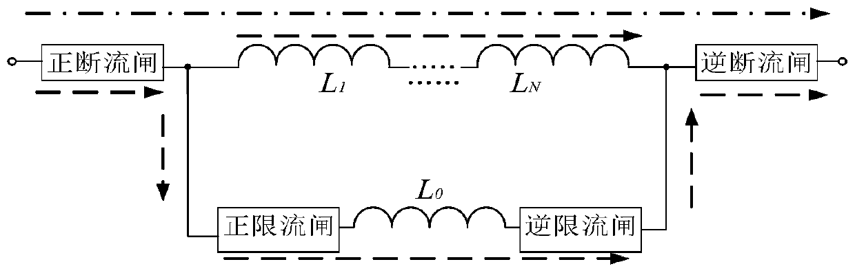
[0037] like figure 1 As shown, the direction along the dotted line or dot-dash line (from left to right) is positive, and vice versa is negative, and the positive and negative directions are defined in this way below. The DC circuit breaker consists of a reactor L 1 , L 2 …L n After series connection with L 0 composed in parallel. Reactor L 0 Both ends are equipped with a positive current-limiting gate and a negative current-limiting gate, which are used to disconnect the reactor L when the forward current and reverse current flow respectively. 0 where branch. The positive current breaking gate and the reverse current breaking gate are respectively arranged on the two terminal sides of the DC circuit breaker, and play the role of controlling the opening of the entire DC circuit breaker when the forward current and the reverse current flow respectively.

[0038] A...


PUM


Abstract

The invention relates to a design method of a direct-current circuit breaker for a flexible direct-current transmission system. The method includes the following steps that: S1, the total topology model of the circuit breaker is established; S2, a forward and reverse current-limiting gate topology model is established; S3, the conversion of the different operation modes of the circuit breaker areset; and S4, the current stress and voltage stress of the circuit breaker which appear when an inter-polar fault occurs on a flexible direct-current transmission line are determined, wherein the circuit breaker has three working states, namely, a normal operation mode, a current-limiting operation mode and a fault isolation mode. On the basis of the mutual conversion of the three states, the circuit breaker can operate in a low-reactance mode during normal operation, enters a current-limiting state when a fault occurs, so as to operate in a high-reactance mode to limit fault current, and finally isolates the fault, and therefore, system equipment can be well protected; and the circuit breaker can integrate a reactor current limiting function by means of topological conversion, so that thecircuit breaker can have a current limiting mode. Compared with the prior art, the design method of the present invention has the advantages of excellent static performance, ultra-high breaking speedand the like.

Description

technical field [0001] The invention relates to the technical field of hybrid direct current circuit breakers, in particular to a design method for a direct current circuit breaker used in a flexible direct current transmission system. Background technique [0002] The DC grid has the characteristics of "low inertia and low impedance", which makes the fault current increase rapidly after a short-circuit fault, causing heavy losses to the equipment in the DC grid. This requires that the fault isolation equipment must quickly and effectively cut off the fault line and isolate the fault after the fault occurs. Therefore, the research and development of DC circuit breakers has always been the focus and difficulty in the development of DC power grids. Among them, the hybrid DC circuit breaker has excellent static characteristics and super fast breaking capacity, which makes it very likely to be used in the future power grid. [0003] In order to deal with many problems such as ...

Claims


Application Information

Patent Timeline
Patent Type & Authority Patents(China)
IPC IPC(8): H02H7/26
Inventor 邓祥力贾声昊胡碧伟张乾波
Owner SHANGHAI UNIVERSITY OF ELECTRIC POWER
Features
  • R&D
  • Intellectual Property
  • Life Sciences
  • Materials
  • Tech Scout
  • Unparalleled Data Quality
  • Higher Quality Content
  • 60% Fewer Hallucinations
Learn More