Device and method for preventing head and tail cutting amounts of flying shear from being excessively large

A cutting head and flying shear technology, applied in the field of metallurgical steel rolling, can solve the problem of excessively large cutting tails, and achieve the effects of improving the cutting tail precision, improving the yield and avoiding the excessive cutting tails.

Active Publication Date: 2019-05-28
HEBEI PUYANG IRON & STEEL
View PDF9 Cites 11 Cited by
  • Summary
  • Abstract
  • Description
  • Claims
  • Application Information

AI Technical Summary

Problems solved by technology

[0003] The technical problem to be solved in the present invention is to provide a device and method for preventing the excessive cutting head and tail of the flying shear, reduce the length of the cutting head and tail of the intermediate billet, avoid the problem of excessive cutting head and tail cutting of the intermediate billet, and reduce the Consumption, improve material yield, reduce production cost

Method used


Image

  • Device and method for preventing head and tail cutting amounts of flying shear from being excessively large
  • Device and method for preventing head and tail cutting amounts of flying shear from being excessively large
  • Device and method for preventing head and tail cutting amounts of flying shear from being excessively large

Examples


Embodiment Construction

[0029] Below in conjunction with embodiment the present invention is described in further detail:

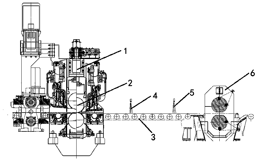
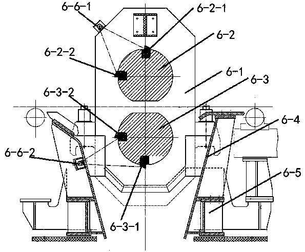
[0030] Such as Figure 1 to Figure 3 Shown, a kind of device that prevents fly-shearing head and tail from being too large, comprises rough rolling mill 1, transport rail 3, flying shear mechanism 6 and flying shear control system, rough rolling mill 1 is provided with rough roll 2, transport track 3 one end It is connected to the rough rolling mill 1, and the other end is connected to the flying shear mechanism 6. The upper end of the transportation track 3 is provided with a thermal detection device I4 and a thermal detection device II5 in sequence. The distance between the thermal detection device II5 and the flying shear mechanism 6 is smaller than the distance between the thermal detection device I4 and the flying shear The distance between the mechanism 6, the thermal detection device I4 and the thermal detection device II5 are connected to the flying shear control system,...


PUM


Abstract

The invention discloses a device and method for preventing the head and tail cutting amounts of a flying shear from being excessively large and belongs to the technical field of metallurgical steel rolling. The device comprises a roughing mill, a conveying rail, a flying shear mechanism and a flying shear control system. A roughing roll is arranged on the rough mill. One end of the conveying railis connected with the roughing mill, and the other end of the conveying rail is connected to the flying shear mechanism. The upper end of the conveying rail is provided with a thermal detection deviceI and a thermal detection device II in sequence, and the thermal detection device I and the thermal detection device II are both connected with the flying shear control system. The flying shear mechanism comprises a flying shear frame, an upper rotating drum and a lower rotating drum, wherein the upper rotating drum and the lower rotating drum are arranged on the flying shearing frame, the upperrotating drum is provided with an upper head cutting shear blade and an upper tail cutting shear blade, the lower rotating drum is provided with a lower head cutting shear blade and a lower tail cutting shear blade, and the upper head cutting shear blade, the upper tail cutting shear blade, the lower head cutting shear blade and the lower tail cutting shear blade are all connected to the flying shear control system. The device and method for preventing the head and tail cutting amounts of the flying shear from being excessively large reduce the head cutting length and tail cutting length of amiddle blank, avoids the head and tail cutting lengths of the middle blank from being excessively large, reduces the consumption of the middle blank, improves the outturn percentage and reduces production cost.

Description

technical field [0001] The invention relates to a device and a method for preventing excessive cutting of a flying shear head and tail, and belongs to the technical field of metallurgy and steel rolling. Background technique [0002] In the continuous rolling production process of ordinary steel rolling workshops, the intermediate billet needs to be cut head and tail by fly shearing between the rough rolling process and the finish rolling process. Cutting the head and tail is a process requirement to ensure the normal operation of production. According to the process requirements, The intermediate billet coming out of the rough rolling mill must rely on the flying shear between rough and finish rolling to complete the head and tail cutting of the intermediate billet, so as to ensure that the intermediate billet can be smoothly bitten into the finishing rolling unit, that is, to ensure the rolling quality of the intermediate billet. Reduce the accident rate of steel biting in...

Claims


Application Information

Patent Timeline
IPC IPC(8): B21B15/00
Inventor 安海珍张珩刘红海王中山高新顺李凯杰郑磊关秀格刘柱
Owner HEBEI PUYANG IRON & STEEL
Why Eureka
Try Eureka