
Continuous tube mill control system and method

A technology for unit control and continuous rolling, which is applied in rolling mill control devices, metal rolling, metal rolling, etc., can solve the problems of long distance transmission, poor anti-interference ability, and low transmission accuracy, so as to save cable costs and reduce Line loss and capacitive reactance, the effect of improving transmission accuracy and stability

Active Publication Date: 2020-11-03
TAIYUAN HEAVY IND
View PDF4 Cites 0 Cited by
  • Summary
  • Abstract
  • Description
  • Claims
  • Application Information

AI Technical Summary

Problems solved by technology

[0004] The inventor found at least the following problems in the prior art: the control modules are centrally placed in the electrical room, so that the distance between the transmission device and the external mechanisms is relatively long, and the long-distance control leads to low transmission accuracy and poor anti-interference ability

Method used


Image

  • Continuous tube mill control system and method

Examples


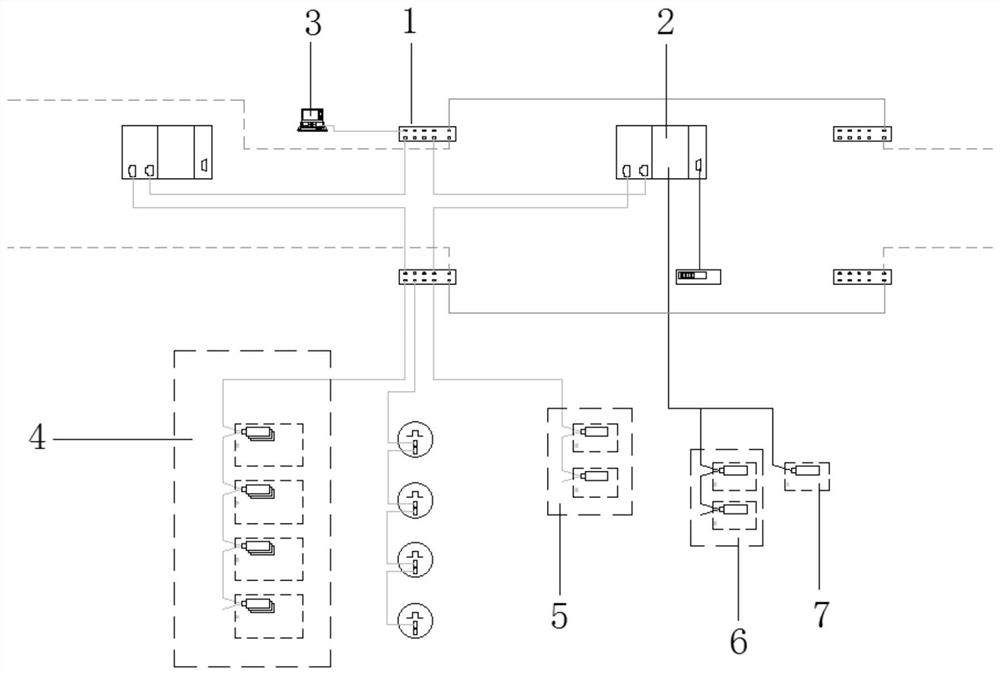
Embodiment Construction

[0024] In order to make the purpose, technical solution and advantages of the present invention clearer, the technical solution of the present invention will be clearly and completely described below in conjunction with specific embodiments of the present invention and corresponding drawings. Apparently, the described embodiments are only some of the embodiments of the present invention, but not all of them. Based on the embodiments of the present invention, all other embodiments obtained by persons of ordinary skill in the art without making creative efforts fall within the protection scope of the present invention.

[0025] The technical solutions provided by the embodiments of the present invention will be described in detail below in conjunction with the accompanying drawings.

[0026] An embodiment of the present invention provides a control system for a continuous pipe rolling unit. The continuous pipe rolling unit includes a plurality of mechanisms connected in sequence...


PUM


Abstract

The invention discloses a continuous rolling tube unit control system and method. The system comprises a plurality of electrical rooms, each electrical room corresponds to one mechanism of a pluralityof mechanisms correspondingly, the electrical rooms are placed nearby with the corresponding mechanisms, each electrical room is internally provided with a first PLC, a second PLC and a transmissiondevice, each first PLC is connected with the corresponding mechanism through the corresponding transmission device, each second PLC is used for adjustment and control of work environment information and upstream information of the corresponding transmission device, and the first PLCs and the second PLCs are in electric connection and are in electric connection with an engineer station correspondingly. According to the continuous rolling tube unit control system and method, the multiple electrical rooms are formed by splitting, each electrical room is arranged nearby at the corresponding mechanism, the cable lengths between the transmission devices and the corresponding mechanisms are relatively short, the transmission accuracy and stability are improved, the cable cost is saved, the work environment information and the upstream information of the transmission devices are adjusted and controlled through the second PLCs, and management and maintenance performed on the split electrical rooms are facilitated.

Description

technical field [0001] The invention relates to the technical field of steel pipe forming, in particular to a control system and method for a continuous pipe rolling unit. Background technique [0002] The steel pipe continuous rolling mill consists of multiple main equipment, and each main equipment contains multiple mechanisms. For example, a common continuous pipe rolling unit includes: annular furnace, piercer, capillary traverse, continuous pipe mill, reheating furnace, stretching and reducing machine, cooling bed, pipe sawing, straightening machine, ash blowing , Flaw detector, packaging and collection mechanism. Each mechanism runs under the drive of a motor, and the motor is connected to a control module (such as a PLC) through a transmission device (such as a frequency converter), so that the operation of each mechanism is carried out under the control of the control module. The number of mechanisms in the continuous pipe rolling unit is relatively large, resultin...

Claims


Application Information

Patent Timeline
Patent Type & Authority Patents(China)
IPC IPC(8): B21B37/78
Inventor 闫文秀刘国栋李晓君秦捷赵旭李忠武葛晓燕张菁
Owner TAIYUAN HEAVY IND
Learn More