Burner, burner assembly and gas stove

A gas stove and burner technology, which is applied in the field of gas stoves, can solve the problems of heat waste and low heat absorption efficiency, and achieve the effects of efficient utilization, efficient absorption and utilization.

Pending Publication Date: 2019-05-28
GREE ELECTRIC APPLIANCES INC
View PDF0 Cites 0 Cited by
  • Summary
  • Abstract
  • Description
  • Claims
  • Application Information

AI Technical Summary

Problems solved by technology

[0004] Therefore, the technical problem to be solved by the present invention is to overcome the defects that the heat absorption efficiency of the pots in the prior art is not high and the heat generated by the gas is wasted.

Method used


Image

  • Burner, burner assembly and gas stove
  • Burner, burner assembly and gas stove
  • Burner, burner assembly and gas stove

Examples


Embodiment 1

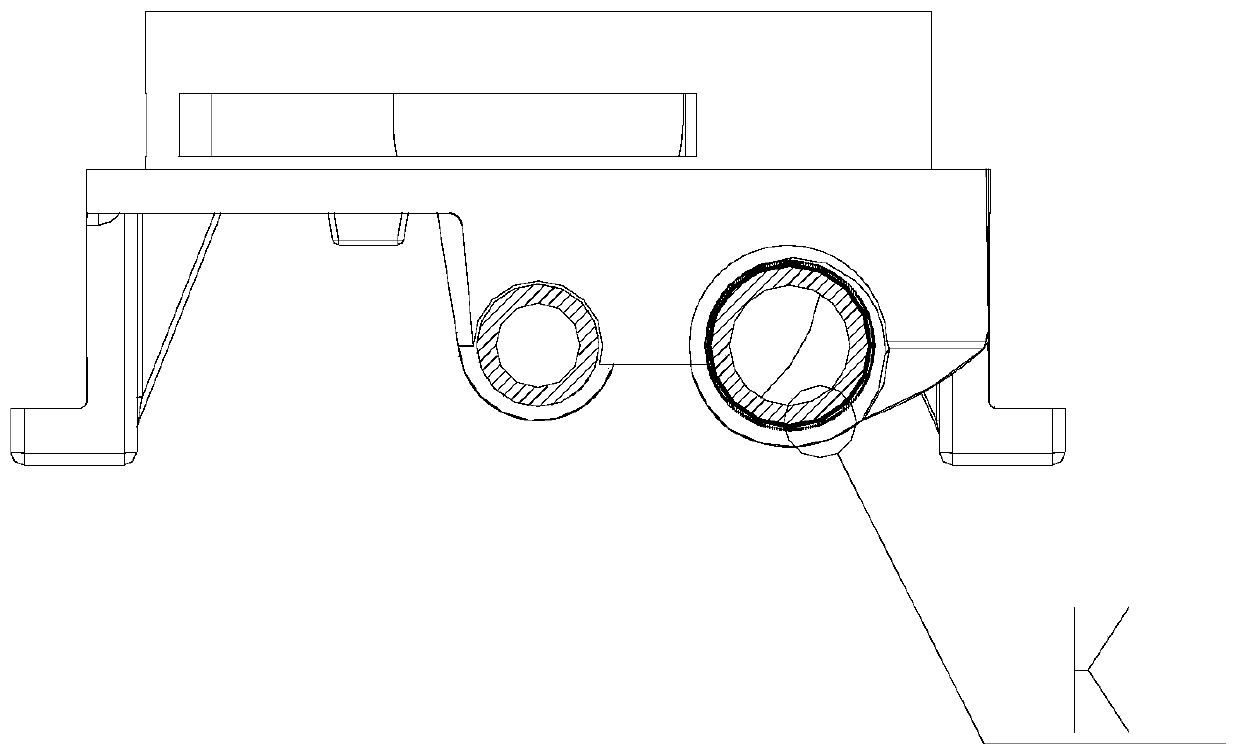
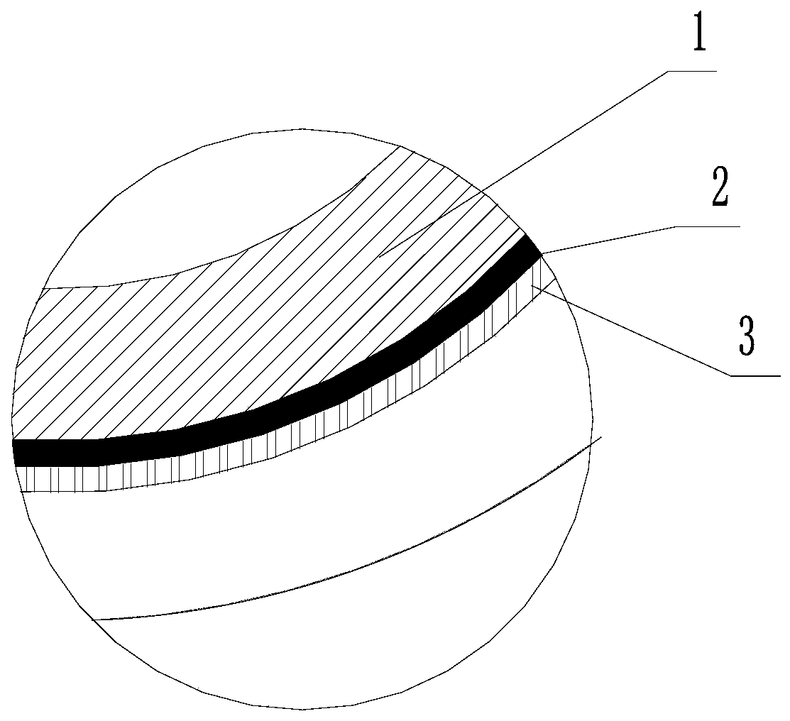
[0034] The present invention provides a furnace head, at least a part of which is provided with a heat recovery part, such as figure 2 As shown in area K, the heat recovery unit includes: image 3 As shown, the insulating layer 2 coated on the outside of the furnace head 1, and the cold end 3 arranged at the position where the insulating layer is in contact with the air.

[0035] In the prior art, the heat transfer path is: heating element→hot end→isolation layer→cold end. The heating element is equivalent to the burner in this embodiment, and the hot end is often made of a metal plate. In this application, the hot end is directly canceled, and the heating element (burner body) is directly used as the hot end. After the heating element and the hot end are combined, the heat transfer path is now: the heating element (burner body) → Isolation layer → cold end, the above method makes the transfer path shorter, so that the heat transfer is faster and more direct. At this time, t...

Embodiment 2

[0050] This embodiment provides a burner assembly, including at least one burner provided in Embodiment 1.

Embodiment 3

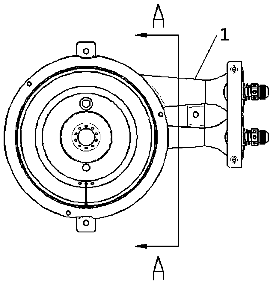
[0052] This embodiment provides a gas cooker, such as figure 1 As shown, at least one burner head provided in Embodiment 1 or the burner head assembly provided in Embodiment 2 is included. An insulating layer coated on the outside of at least a portion of the burner head, and a cold end disposed at a portion of the insulating layer in contact with air. After the burner head receives the heat from the gas, the above method shortens the heat transfer path inside the burner head, so that the heat energy can be transferred faster and more directly. At this time, most of the heat generated by the burner head after flame combustion will be used On the burner head, after the burner head is heated by the flame, the above-mentioned method shortens the heat transfer path inside the burner head, so that the heat energy can be transferred faster and more directly. Most of them will be used on the burner head, so that the temperature of the burner head is higher, thereby improving the hea...


PUM


Abstract

The invention provides a burner, a burner assembly and a gas stove. At least one part of the burner is provided with a heat recovery part. The heat recovery part comprises an isolation layer and a cold end. The burner is externally coated with the isolation layer. The cold end is arranged in the position, making contact with air, of the isolation layer. In the burner, the burner assembly and the gas stove, a hot end is canceled directly, a heating body (the burner) directly serves as a hot end to be used, and after the heating body and the hot end are combined, the heat transfer path is the heating body (the burner)->the isolation layer->the cold end. With the above mode, the transfer path becomes short, thus heat energy is transferred faster and more directly, at the moment temperature ofthe hot end is higher than that of a traditional hot end, the temperature difference of the hot end and the cold end is larger, and heat energy is converted into more electric energy. In addition, heat energy of the burner during working of the gas stove is selected to be converted into electric energy, temperature of the burner during working of the gas stove can be lowered effectively, and energy efficiency and other properties of the gas stove can be promoted effectively.

Description

technical field [0001] The invention relates to the technical field of burners, in particular to a burner with high combustion efficiency and a gas stove containing the burner. Background technique [0002] During the use of gas stoves, the heat generated by gas combustion is not only used to heat the pot, but also a large amount of heat will be lost to the atmosphere. Most of these heat losses are wasted, and it is also a loss to the gas. . In order to improve the heat energy utilization rate of gas, two improvements are often made in the prior art: 1. Improve the heat absorption efficiency of the gas stove, so that as little heat as possible can be emitted to the outside, and more heat can be used to raise the temperature; 2. , Recycle the heat lost outside the gas stove. [0003] In the prior art, due to the limitation of the space of the gas stove and the kitchen itself, there are few energy recovery devices that can be arranged outside the gas stove, so it is difficul...

Claims


Application Information

Patent Timeline
IPC IPC(8): F23D14/46H02N11/00
Inventor 刘书兴孙娅丽杨海潮林玉绵孙帅叶伟林刘小平丁泺火孟得浩
Owner GREE ELECTRIC APPLIANCES INC
Why Eureka
Try Eureka