Hoop assembly for electronic scales

An electronic scale and hoop technology, which is applied in the field of electronic scales, can solve the problems of low construction cost, constrain strip electronic scales and inflators, etc., and achieve the effects of increasing the working cycle, low construction cost, and improving the rigidity of the structure.

Inactive Publication Date: 2019-05-28
SHAANXI JOIN CREATE SCI & TECH
View PDF0 Cites 0 Cited by
  • Summary
  • Abstract
  • Description
  • Claims
  • Application Information

AI Technical Summary

Problems solved by technology

[0004] In order to solve the above problems, the present invention provides a hoop for electronic scales, which effectively avoids the defects in the prior art that restrict the size of strip electronic scales and inflator monitoring simulation parts, and the construction cost is not low

Method used


Image

  • Hoop assembly for electronic scales
  • Hoop assembly for electronic scales

Examples


Embodiment Construction

[0015] The present invention will be further described below in conjunction with examples.

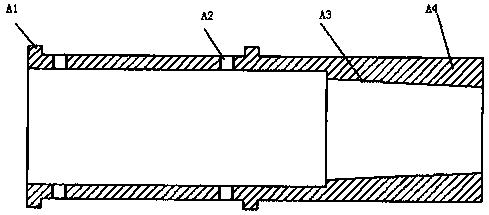
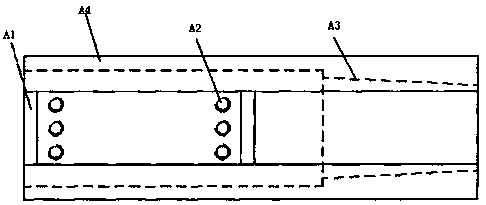
[0016] like Figure 1-Figure 2 As shown, the hoop used for electronic scales in this embodiment includes a limit step A1, a wire groove A2, a connecting circular platform body A3 and a clamp A4, and a pair of limit steps A1 are equipped on the outer surface of the clamp , the interval between a pair of limit ladders A1 is the same as the span of the connecting strip head of the simulated parts.

[0017] One side of the clamp A4 is equipped with a plurality of wire connection slots A2.

[0018] The number of wire splicing slots A2 is the same as the number of blind openings on the head of the connecting strip of the simulation part.

[0019] The wire connection groove A2 is connected with the blind wire on the head of the dummy subsection via the tensioning lead screw.

[0020] One side of the inner side of the clamp A4 is equipped with a connecting cone A3.

[0021] The structure i...


PUM


Abstract

The invention relates to a hoop assembly for electronic scales. The hoop assembly comprises a pair of limiting steps, wire joint grooves, a circular table body for coupling and a clamp; the outer surface of the clamp is provided with the limiting steps, and spans of branch connecting strip heads of interval simulation parts between the limiting steps are the same. One side of the clamp is providedwith the wire joint grooves. The number of the wire joint grooves is the same as that of blind ports in the branch connecting strip heads of the simulation parts. The wire joint grooves are connectedwith the blind ports in the branch connecting strip heads of the simulation parts through tension screws. One side of the interior of the clamp is provided with the circular table body for coupling.The defects that the sizes of strip-shaped electronic scales and inflator monitoring simulation components are constrained and the construction cost is high in the prior art are effectively avoided.

Description

technical field [0001] The invention relates to the technical field of electronic scales, in particular to a hoop used for electronic scales. Background technique [0002] In the supporting system of the inflator monitoring simulation part, the connecting strips of the simulation parts and the strip-shaped electronic scales must be connected through a joint body, and the joint body must withstand all the actions and twists that the simulation part will be subjected to during the monitoring of the inflator Effects, including airflow impact, lifting action, edge impact, torsion action, rotation action and error impact, and the superposition of several impacts and torsion, the impact situation is not simple and cumbersome, and the joint frequently reciprocates and decomposes and Equipped to make the standard of circular limit error smaller. [0003] Now, the coupling often uses not simple coupling equipment, which has a large cycle limit error, and the hardness of the coupling...

Claims


Application Information

Patent Timeline
Patent Type & Authority Applications(China)
IPC IPC(8): G01G19/52G01G23/00
Inventor 不公告发明人
Owner SHAANXI JOIN CREATE SCI & TECH
Why Eureka
Try Eureka