
Thin plate metallographical thermal embedding method

A technology of hot embedding and thin plate, applied in the preparation of test samples, etc., can solve the problems of capillary action, grinding sample corrosion, corrosion of metallographic surface, etc., and achieve the effect of reducing sample preparation cost, improving efficiency and improving success rate

Active Publication Date: 2019-05-28
INST OF RES OF IRON & STEEL JIANGSU PROVINCE +2
View PDF9 Cites 3 Cited by
  • Summary
  • Abstract
  • Description
  • Claims
  • Application Information

AI Technical Summary

Problems solved by technology

The above patents all have small gaps between the thin plate and the holder, and between the thin plate and the thin plate, resulting in capillary action, abrasive corrosion, water stains, and corrosion of the metallographic surface

Method used


Image

  • Thin plate metallographical thermal embedding method
  • Thin plate metallographical thermal embedding method

Examples


Embodiment 1

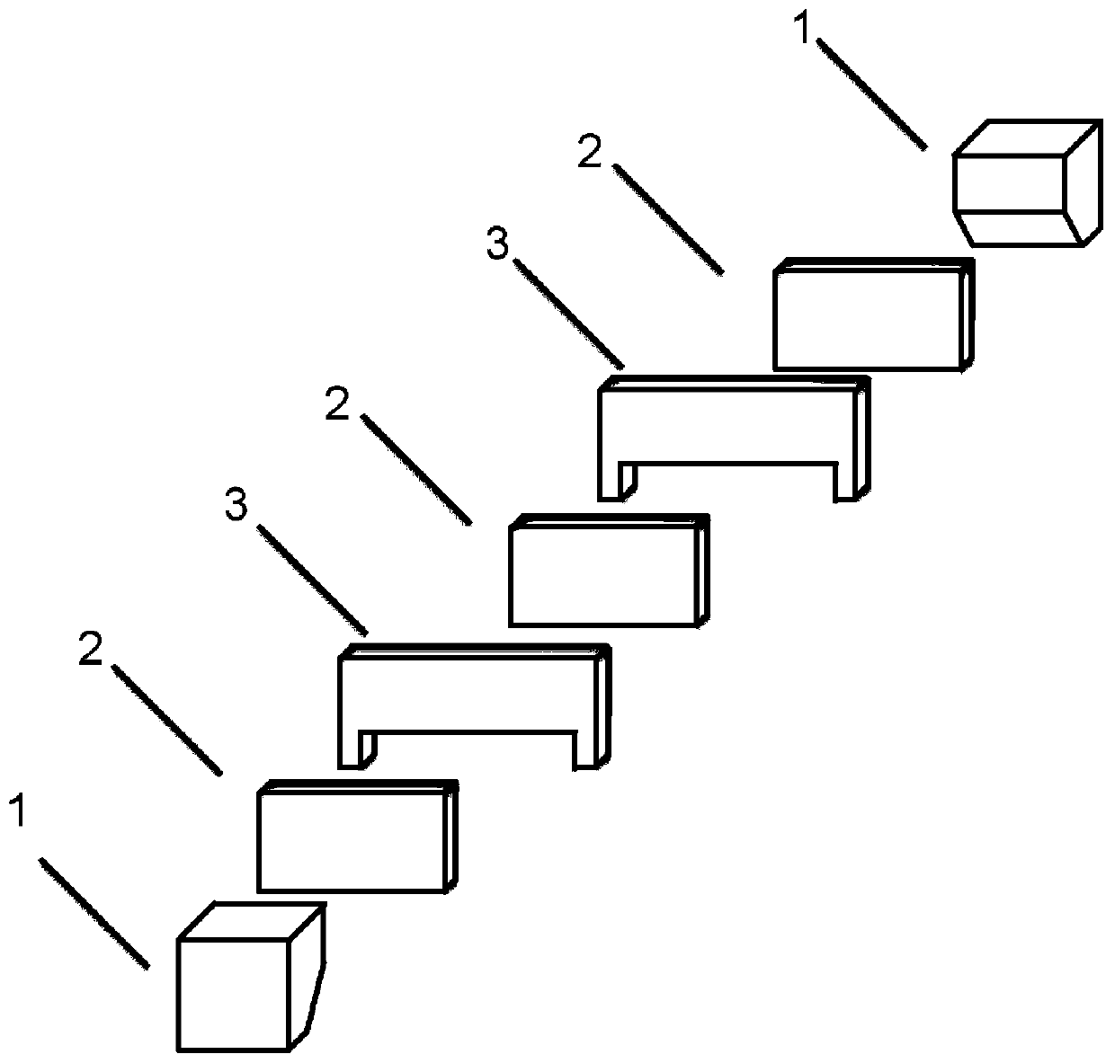
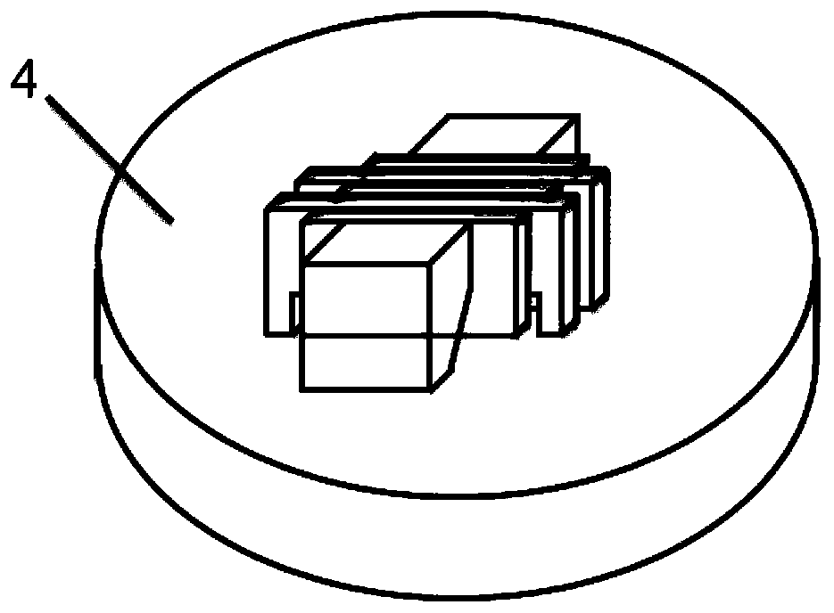
[0028] A single piece of DC04 deep-drawn IF steel sheet (thickness 0.8mm) was inlaid by hot inlay method, and the size and uniformity of ferrite structure were mainly observed. Using the thin plate thermal embedding method in the present invention, first use the inlay material alone to process it into a thermosetting resin block (thickness 4.0mm) with a notch, and the side length of the notch (2.0mm), place the thin plate with the notched thermosetting resin Between the blocks, the whole follows figure 2 Place it on the lower mold platform of the mounting machine, select a heating temperature of 180°C, a heating time of 4 minutes, a pressure of 250 bar, a high-speed cooling, and a water cooling time of 4 minutes for mounting. The cross-section of the thin plate is flat, there is no water stain on the surface after corrosion, and the overall metallographic structure is clean and convenient for shooting.

Embodiment 2

[0030] Eight pieces of DX53D+Z galvanized sheets (thickness 0.5mm, length 6.0mm, width 4.0mm) were inlaid by hot mosaic method, mainly to observe the structure of the zinc layer. Adopt thin plate thermal embedding method in the present invention, at first use inserting material to inlay and process thermosetting resin sheet (thickness 0.2mm, length 10.0mm, width 6.0mm), its notch size (length 8.0mm, width 2.0mm); processing resin Block (4.0mm), notch side length (2.0mm). Adjacent thin plate samples are separated by thermosetting resin sheets with notches, and the two ends are clamped and fixed by thermosetting resin blocks with notches, such as figure 1 shown. Put the whole into the hot mounting machine, such as figure 2 As shown, add resin inserts, select heating temperature 190°C, heating time 6min, pressure 280bar, select medium speed cooling, water cooling time 6min, and mount. There is no gap between the sections of the galvanized sheet, the corroded surface of the sa...


PUM


Abstract

The invention discloses a thin plate metallographical thermal embedding method. Resin embedding materials are processed into thermocured resin flakes and resin blocks, and gaps are machined in the thermocured resin flakes and resin blocks. When there is one thin plate sample, the thin plate sample is fixed by the thermocured resin blocks with the gaps, and put into a thermal embedding machine as awhole, and the resin embedding materials are added for embedding; when there are many thin plate samples, every two adjacent thin plate samples are separated through the thermocured resin blocks withthe gaps, the two ends of each thin plate sample are clamped and fixed through the thermocured resin blocks with the gaps, the thin plate samples are put into the thermal embedding machine as a whole, and the resin embedding materials are added for embedding. According to the method, the sample preparation cost is low, the thickness of the thin plates is not required, and the thin plate embeddingefficiency can be improved; moreover, the capillary phenomenon cannot occur, and the metallographical shooting success rate is increased.

Description

technical field [0001] The invention belongs to a metallographic sample preparation technology of metal materials, in particular to a thin plate metallographic hot embedding method. Background technique [0002] For thin-plate samples, if the sample preparation and grinding operations are performed without fixing or inlaying, the section will be uneven, and it is easy to cause mechanical damage to the sample preparation personnel. Metallographic mounting generally adopts three methods: mechanical, cold mounting, and thermal mounting. Mechanical mounting is time-consuming and laborious, with low efficiency and insufficient stability, causing stress concentration and even deformation to thin plate samples; cold mounting liquid mounting materials take a long time to solidify, and the mounting cannot be completed in time, and the efficiency is low; hot mounting is a laboratory metallographic sample preparation. The most commonly used method, with high efficiency, the heat-cured...

Claims


Application Information

Patent Timeline
IPC IPC(8): G01N1/36G01N1/44
Inventor 陈刚刘志桥张志建李化龙赵刚
Owner INST OF RES OF IRON & STEEL JIANGSU PROVINCE
Learn More