Hydrothermal management system for fuel cell engine system

An engine system and fuel cell technology, applied in the direction of fuel cell heat exchange, fuel cells, fuel cell additives, etc., can solve the problems of increasing the number of system components, poor quality, and increasing system power consumption, so as to reduce the need for additional components , Eliminate additional requirements, and reduce the effect of additional power consumption

Inactive Publication Date: 2019-05-28
SHANDONG UNIV
View PDF6 Cites 25 Cited by
  • Summary
  • Abstract
  • Description
  • Claims
  • Application Information

AI Technical Summary

Problems solved by technology

[0005] 1. In the existing system, the hydrogen circulation pump is mostly used to recycle the hydrogen, which increases the power consumption of the system;
[0006] 2. In order to ensure the wetness of the electrodes, the existing system is equipped with a humidifying water tank to humidify the anode and cathode of the battery or only the cathode, which increases the number of system components and also increases the space required for the system; in addition, when the stack proton membrane is larger When it is thick, not humidifying the anode of the stack will easily cause the anode side of the membrane to dry up;
[0007] 3. The existing system needs an additional cold source when cooling the air, which increases the investment cost
When the temperature of the pressurized hydrogen is high, the existing system does not cool or the cooling effect is not good, which is not conducive to ensuring the working efficiency of the stack

Method used


Image

  • Hydrothermal management system for fuel cell engine system

Examples


Embodiment Construction

[0033] The present disclosure will be further described below in conjunction with the accompanying drawings and specific embodiments.

[0034] It should be pointed out that the following detailed description is exemplary and intended to provide further explanation to the present application. Unless defined otherwise, all technical and scientific terms used herein have the same meaning as commonly understood by one of ordinary skill in the art to which this application belongs.

[0035] It should be noted that the terminology used here is only for describing specific implementations, and is not intended to limit the exemplary implementations according to the present application. As used herein, unless the context clearly dictates otherwise, the singular is intended to include the plural, and it should also be understood that when the terms "comprising" and / or "comprising" are used in this specification, they mean There are features, steps, operations, means, components and / or ...


PUM


Abstract

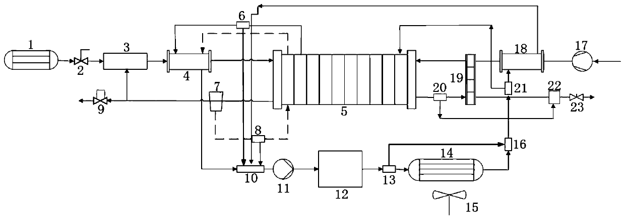
The invention provides a hydrothermal management system of a fuel cell engine system, which comprises a hydrogen supply system, an air supply system and a heat dissipation system, wherein the hydrogensupply system is configured to recycle hydrogen through an ejector, to conduct hydrogen humidification through water vapor generated by a fuel cell stack, and to conduct hydrogen heating through cooling water at an outlet of the fuel cell stack, so that after the temperature and humidity of hydrogen meet the water balance adjusting requirement, the hydrogen enters the fuel cell stack to participate in a reaction; the air supply system is configured to compress air and humidify dry air entering the fuel cell stack through wet air at the outlet of the fuel cell stack, so that the air enters thefuel cell stack to participate in the reaction after the temperature and the humidity of the air reach set requirements; and the heat dissipation system is configured to perform heat dissipation on part of cooling water at the outlet of the fuel cell stack, mix the cooling water which is subjected to heat dissipation with the other part of cooling water which is not subjected to heat dissipationand feed the mixture into the fuel cell stack again.

Description

technical field [0001] The present disclosure relates to the technical field of fuel cell water heat management, in particular to a water heat management system of a fuel cell engine system. Background technique [0002] The statements in this section merely mention background art related to the present disclosure and do not necessarily constitute prior art. [0003] The hydrothermal management of fuel cell engine is to effectively control and manage the heat transfer of fuel cell engine from the perspective of system integration and overall, cool the fuel cell and its auxiliary components, reduce system energy consumption and improve the overall performance of the engine. The optimization of water heat management has an important impact on the performance, service life and operational safety of fuel cell engines, and is one of the core key technologies and components in the research and development of fuel cell engines. [0004] As far as the inventor knows, the existing h...

Claims


Application Information

Patent Timeline
Patent Type & Authority Applications(China)
IPC IPC(8): H01M8/04089H01M8/04119H01M8/04029H01M8/04014H01M8/04225H01M8/04746H01M8/04828
CPCY02E60/50
Inventor 于泽庭展茂胜王桂华李国祥
Owner SHANDONG UNIV
Why Eureka
Try Eureka